Parts Washer

a washer and washer body technology, applied in the field of parts washers, can solve the problems of increasing costs, increasing costs, and and achieving the effect of reducing the number of jets and increasing the efficiency of the machin

Inactive Publication Date: 2006-11-30
GODDARD EARL FENTON
View PDF3 Cites 11 Cited by
  • Summary
  • Abstract
  • Description
  • Claims
  • Application Information

AI Technical Summary

Problems solved by technology

Both of these methods however have limitations.
Providing higher pressure from the pump may require changing the pump itself and associated piping, leading to increased costs.
Reducing the number of jets is also often not practical as this reduces the area within the parts washer impacted by the jets.
This, however, can lead to increased likelihood of the jets blocking up.

Method used


Image

  • Parts Washer
  • Parts Washer
  • Parts Washer

Examples


Embodiment Construction

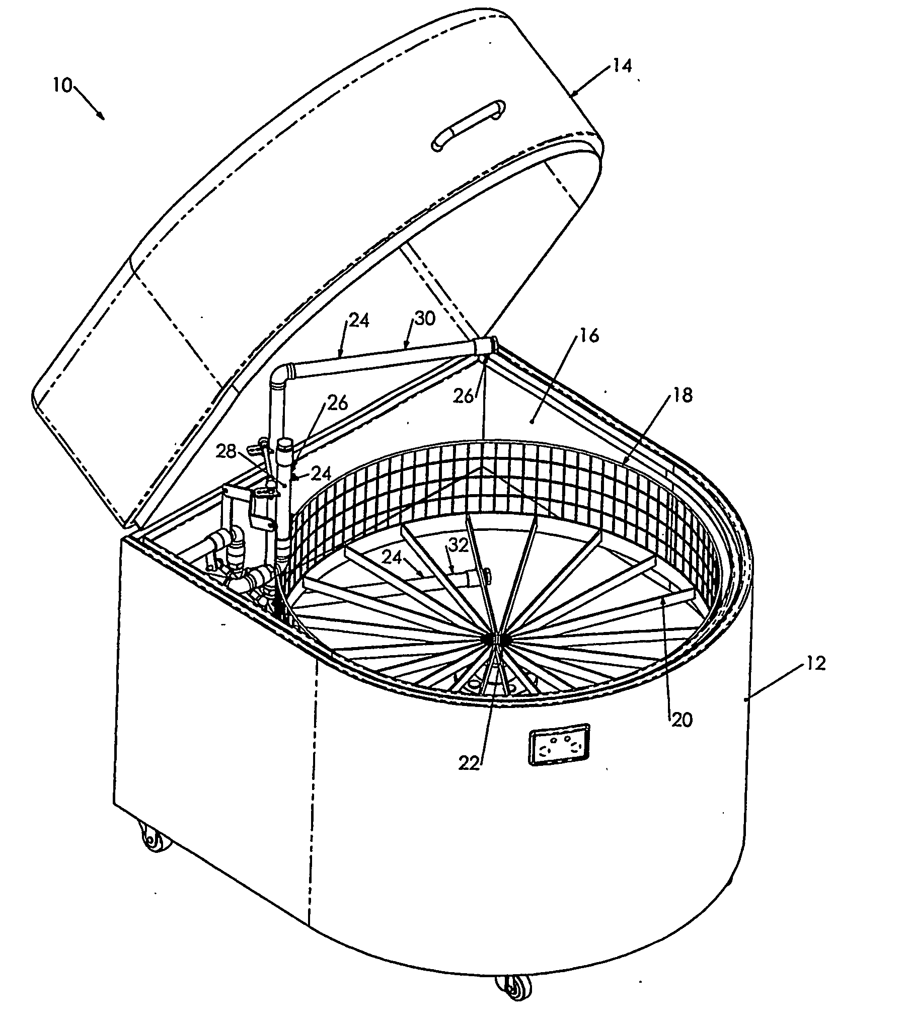
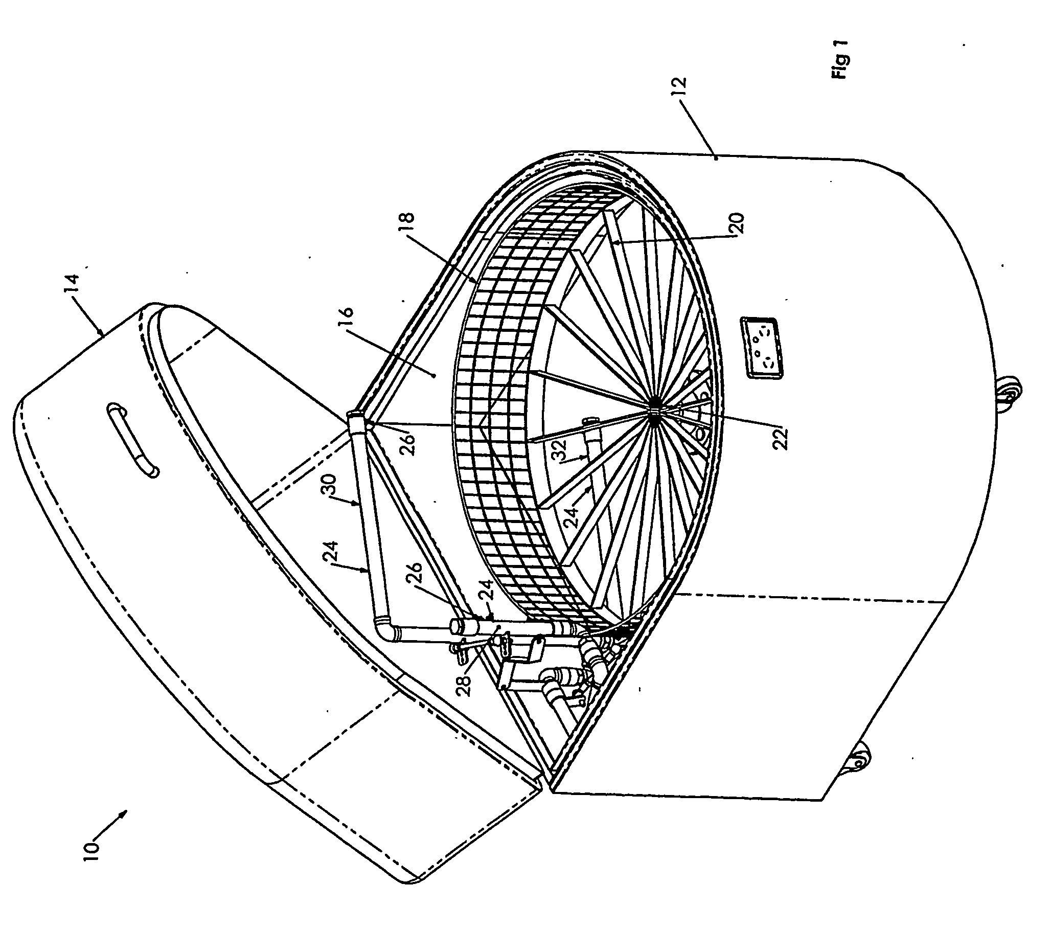
[0028] Referring to the Figures, there is shown a parts washer 10 comprising a cabinet 12 having a lid 14 defining a cleaning chamber 16 within the cabinet 12 when the lid 14 is closed.

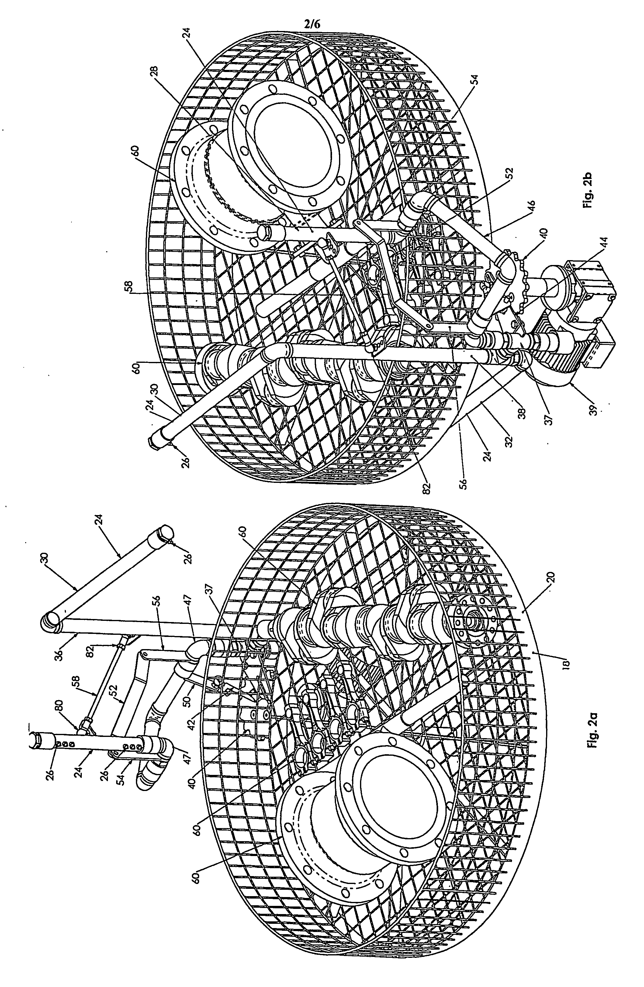
[0029] The parts washer 10 includes a receptacle 18 rotatably mounted within the cleaning chamber 16. The receptacle comprises a circular basket 20 mounted on a central drive shaft 22. In use, parts 60 which are to be washed by the parts washer 10 are placed within the basket 20.

[0030] The parts washer 10 is provided with a receptacle drive means comprising a drive motor (not shown) connected to the drive shaft 22 such that the basket 20 is rotated about the drive shaft 22 in use.

[0031] The parts washer 10 includes a plurality of spray manifolds 24 having spray jets 26 thereon. In the embodiment shown in the drawings, the parts washer 10 includes a vertical spray manifold 28 and first and second horizontal spray manifolds 30 and 32. The vertical spray manifold 28 is arranged adjacent a side of the ...


PUM


Abstract

A parts washer having a cleaning chamber and a receptacle into which parts to be cleaned are placed. The receptacle is rotatably mounted within the cleaning chamber and is rotated by a drive device. One or more spray manifolds are provided, each having a plurality of spray jets arranged to spray cleaning fluid onto the parts in the receptacle. The spray manifolds are moveably mounted within the cleaning chamber and are coupled to the drive device such that the drive device causes reciprocating motion of the spray manifolds.

Description

FIELD OF THE INVENTION [0001] The present invention relates to a parts washer. BACKGROUND OF THE INVENTION [0002] Various industries, such as the automotive industry, require a method of cleaning mechanical components which are subject to a build up of dirt, grease and oil. It is known to provide a parts washer in which the components may be placed to be cleaned. Such washers generally include a cleaning chamber into which the parts are placed and a fluid reservoir in which is stored cleaning fluid. A pump is provided to pump the cleaning fluid from the reservoir into the cleaning chamber via jets within the chamber to clean the parts. The cleaning fluid is then returned to the fluid reservoir. [0003] The effectiveness of the parts washer is determined, at least partly, by the pressure of the cleaning fluid from the jets within the chamber. In order to provide higher pressure jets within the chamber, it is necessary to either increase the pressure provided by the pump or to decrease...

Claims


Application Information

Patent Timeline
Patent Type & Authority Applications(United States)
IPC IPC(8): B08B3/00B08B3/12B08B3/02B08B3/04
CPCB08B3/02B08B3/045B08B3/024
Inventor GODDARD, EARL FENTON
Owner GODDARD EARL FENTON
Why Eureka
Try Eureka