

Electromagnetic wave measuring apparatus
a technology of electromagnetic waves and measuring apparatus, which is applied in the direction of measuring devices, antenna radiation diagrams, instruments, etc., can solve the problem of long measurement period
- Summary
- Abstract
- Description
- Claims
- Application Information
AI Technical Summary
Problems solved by technology
Method used
Image

Examples
1st embodiment
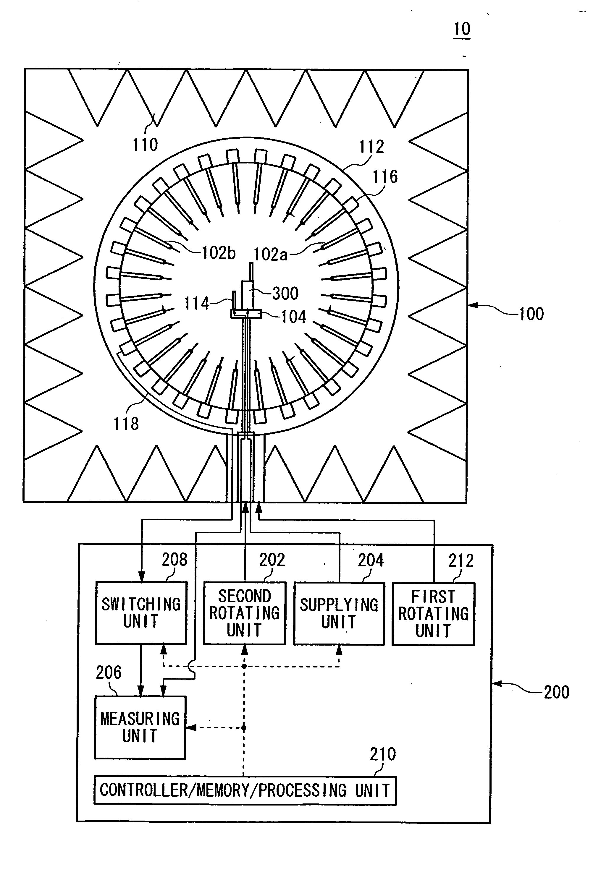
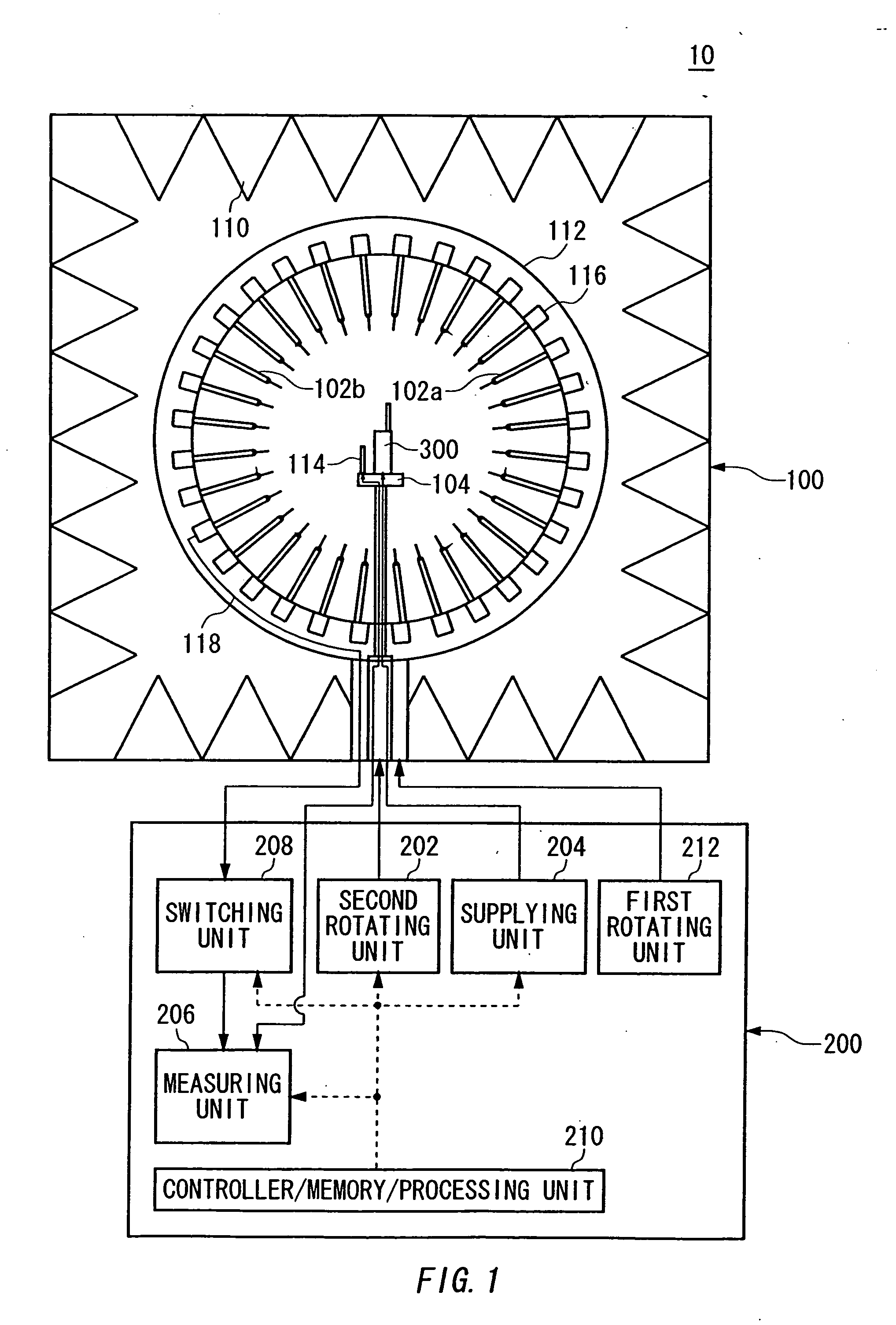
[0035]FIG. 1 illustrates a structure of an electromagnetic wave measuring apparatus 10 according to the first embodiment of the present invention. The electromagnetic wave measuring apparatus 10 includes a mechanism 100 having a holder 104, a plurality of probe antennas 102, an installing unit 112, an electromagnetic wave absorber 110, a fixed antenna 114 and an optical fiber 118; and a processing system 200 having a supplying unit 204, a measuring unit 206, a switching unit 208, a controller / memory / processing unit 210, a first rotating unit 212 and a second rotating unit 202.
[0036] In the present embodiment, an antenna to be measured 300 radiates an electromagnetic wave based on an RF output signal supplied thereto. The holder 104 holds the measured antenna 300. Each probe antenna 102 detects the electromagnetic wave radiated from the measured antenna 300. The installing unit 112 holds the probe antennas 102 on a circle having a center substantially at the holder 104 (hereinafter,...
2nd embodiment
[0054]FIG. 3 illustrates a structure of an electromagnetic wave measuring apparatus 10 according to the second embodiment of the present invention. The electromagnetic wave measuring apparatus 10 includes: a mechanism 100 having a holder 104, a plurality of probe antennas 102, an installing unit 112, an electromagnetic wave absorber 110, a fixed antenna 114 and a receiving antenna 120; and a processing system 200 having a supplying unit 204, a measuring unit 206, a switching unit 208, a controller / memory / processing unit 210, a first rotating unit 212 and a second rotating unit 202. The holder 104, the probe antennas 102, the electromagnetic wave absorber 110, the fixed antenna 114, the first and second rotating units 212 and 202, the supplying unit 204, the measuring unit 206, the switching unit 208 and the controller / memory / processing unit 210 in the present embodiment have the same functions as the corresponding components in the first embodiment shown in FIG. 1.
[0055] The instal...
3rd embodiment
[0058]FIG. 5 illustrates a structure of an electromagnetic wave measuring apparatus 10 according to the third embodiment of the present invention. The electromagnetic wave measuring apparatus 10 includes a mechanism 100 having a holder 104 which holds an antenna to be measured 300, a plurality of probe antennas 102 each of which detects an electromagnetic wave radiated from the measured antenna 300, an installing unit 112 on which the plurality of probe antennas 102 are provided, a cable group 106 containing a plurality of cables for electrically connecting each of the probe antennas 102 and the measuring unit 206 and outputting detection signals respectively indicating the electromagnetic wave detected by the probe antennas 102 to the outside, an electromagnetic wave absorber 108 provided in surroundings of the cable group 106 for absorbing the electromagnetic wave radiated from the measured antenna 300, another electromagnetic wave absorber 110 provided to cover the probe antennas...
PUM
 Abstract
Description
Claims
Application Information