Liquid crystal display apparatus capable of controlling range of viewing angle

a liquid crystal display and viewing angle technology, applied in non-linear optics, static indicating devices, instruments, etc., can solve the problem of inability to perform stable viewing angle control, and achieve the effect of stable viewing angle control

Inactive Publication Date: 2006-11-30
CASIO COMPUTER CO LTD
View PDF12 Cites 45 Cited by
  • Summary
  • Abstract
  • Description
  • Claims
  • Application Information

AI Technical Summary

Benefits of technology

[0010] It is an object of the present invention to provide a liquid crystal display apparatus which is provided with a transverse electric field type liquid crystal display device and can perform stable viewing angle control.
[0039] viewing angle controlling means for receiving a viewing angle selection signal for selection of a viewing angle to be synchronized with the display drive signal, generating a viewing angle controlling voltage different from the display drive signal, and supplying the generated voltage to the third electrode to generate the vertical electric field in the liquid crystal layer of the plurality of pixels, thereby restricting a range of the viewing angle.
[0041] Furthermore, according to the liquid crystal display apparatus based on the second aspect of the present invention, the plurality of first and second electrodes which generate a transverse electric field parallel to the substrate surfaces are provided on the inner surface of one substrate of the liquid crystal display device, and the third electrode which generates a vertical electric field parallel to the thickness direction of the liquid crystal layer is provided on the opposed substrate surface. The first and second signals are supplied to a part between the first and second electrodes to apply a transverse electric field corresponding to image data, and the third signal whose potential varies in synchronization with a change in potential of a signal supplied to the first electrode is applied to the third electrode. As a result, a vertical electric field in a direction substantially parallel to the thickness direction of the liquid crystal layer is applied. Therefore, it is possible to selectively perform wide viewing angle display when driving using the transverse electric field alone and narrow viewing angle display when driving using both the transverse electric field and the vertical electric field.
[0042] Moreover, according to the liquid crystal display apparatus based on the third aspect of the present invention, there are provided: liquid crystal displaying means having the first and second electrodes which generate a transverse electric field parallel to the substrate surfaces, and the third electrode which generates a vertical electric field parallel to the thickness direction of the liquid crystal layer; image displaying means for generating a transverse electric field corresponding to image data to a part between the first and second electrodes; and viewing angle controlling means receiving a viewing angle selection signal for selection of a viewing angle to be synchronized with the display drive signal, and supplying a viewing angle controlling voltage different from the display drive signal to the third electrode to generate the vertical electric field in the liquid crystal layer of the pixel, thereby restricting a range of the viewing angle. Therefore, it is possible to selectively perform wide viewing angle display when driving using the transverse electric field and narrow viewing angle display when driving using both the transverse electric field and the vertical electric field.

Problems solved by technology

Therefore, the viewing angle fluctuates in accordance with the image data, and stable viewing angle control cannot be performed.

Method used


Image

  • Liquid crystal display apparatus capable of controlling range of viewing angle
  • Liquid crystal display apparatus capable of controlling range of viewing angle
  • Liquid crystal display apparatus capable of controlling range of viewing angle

Examples


first embodiment

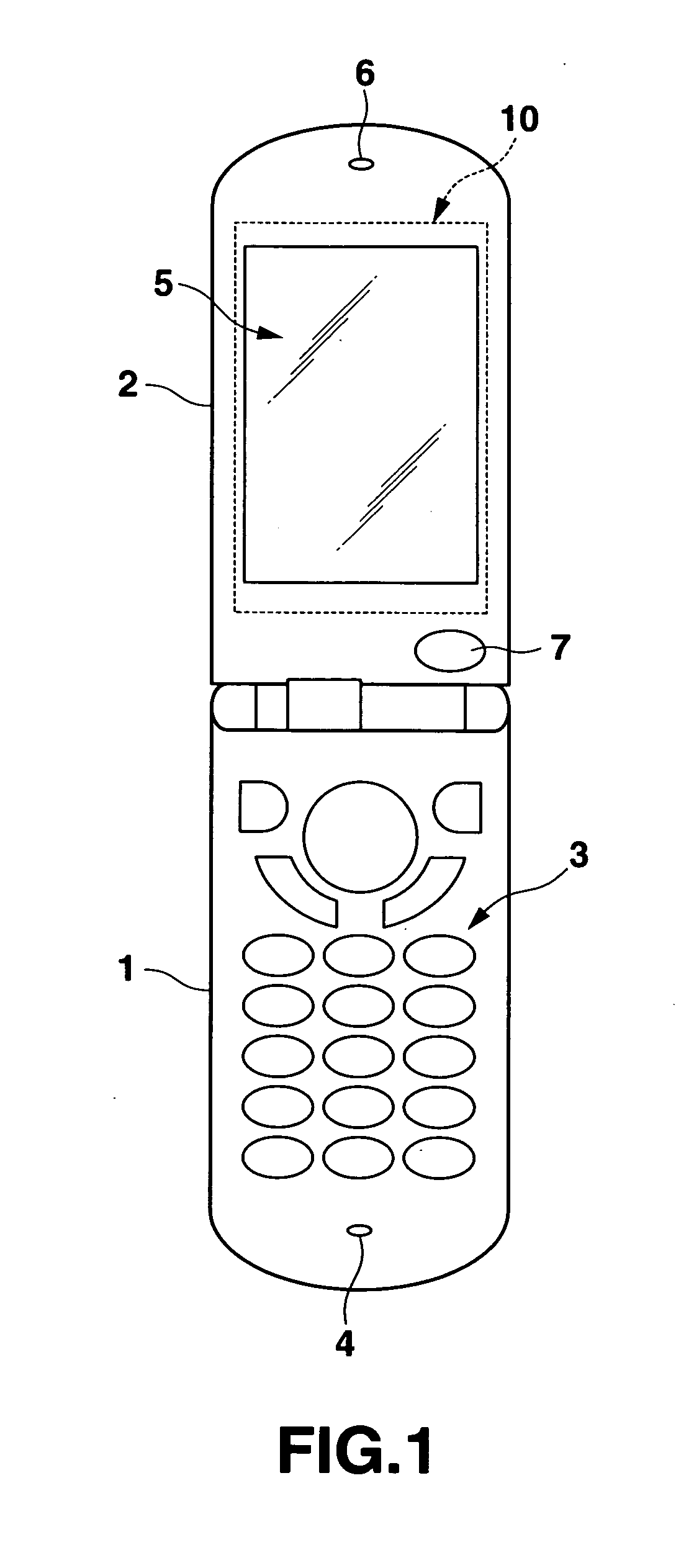
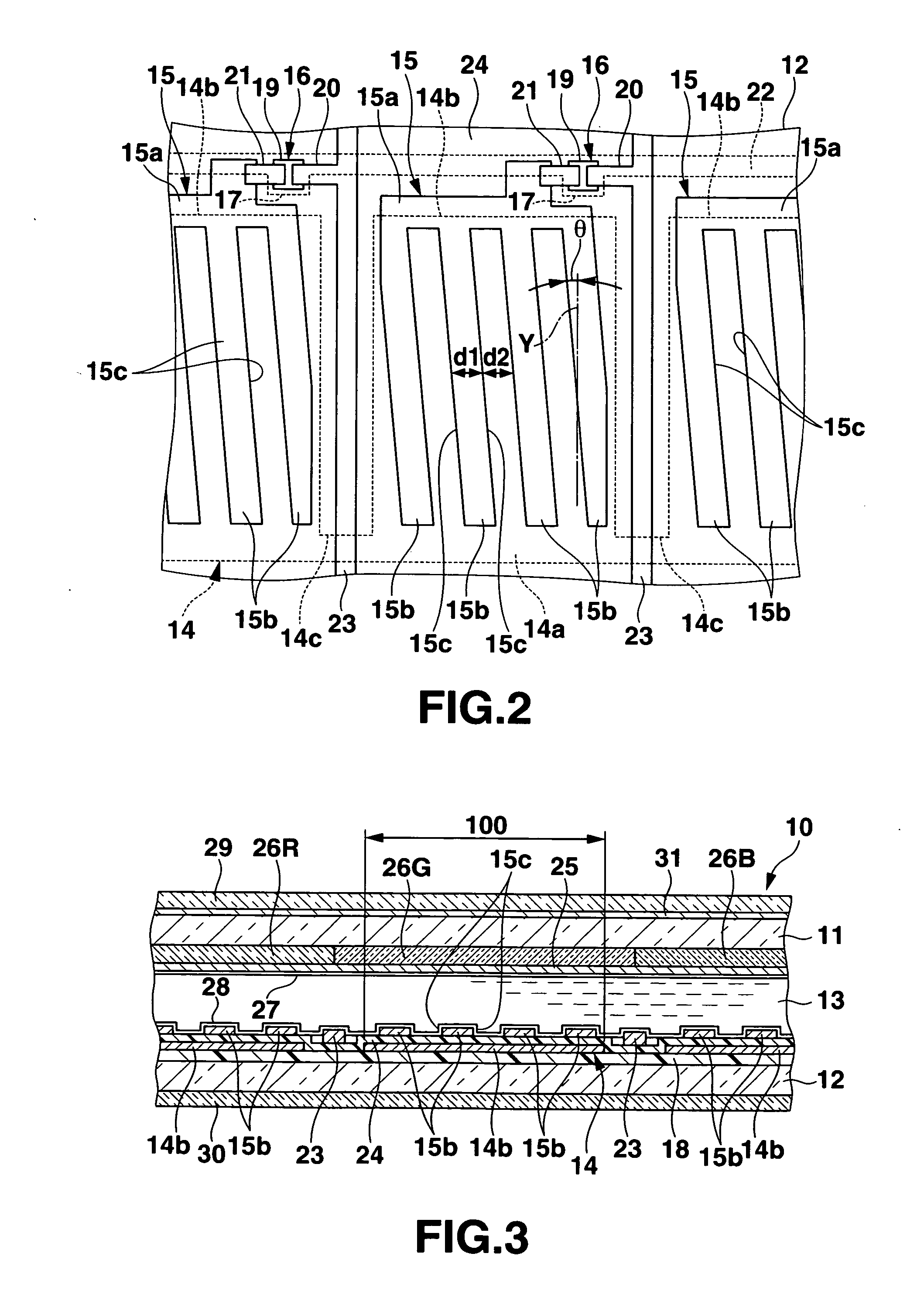
[0061] FIGS. 1 to 15A and 15B show a first embodiment of the present invention, wherein FIG. 1 is a front view of an electronic device including a liquid crystal display apparatus; FIG. 2, a plan view showing a part of one substrate in a liquid crystal display device of the liquid crystal display apparatus; and FIG. 3 is a cross-sectional view showing a part of the liquid crystal display device.

[0062] The electronic device shown in FIG. 1 will be described first. This electronic device is a flip type mobile phone constituted of: a phone main body 1; and a cover body 2 which has a base end pivoted at an end of the phone main body 1 and swivels between an opened state where it protrudes toward the outside of the phone main body 1 as shown in the figure and a closed state where it lies over the phone main body 1. A keyboard portion 3 and a microphone portion 4 are provided on a front surface of the phone main body 1 (a surface on which the cover body 2 is superimposed). A display port...

second embodiment

[0124]FIG. 16 is a plan view showing a part of one substrate in a liquid crystal display device according to a second embodiment of the present invention. It is to be noted that, in this embodiment, like reference numerals denote parts corresponding to those in the first embodiment, thereby eliminating their explanation.

[0125] In a liquid crystal display apparatus according to this embodiment, a signal electrode 15 on an inner surface of a pixel forming electrode substrate 12 in a liquid crystal display device is formed of a slit formed electroconductive film 115a patterned into a shape having a plurality of slits 115c along a direction inclined in one of left and right directions with respect to a vertical direction of a screen of the liquid crystal display device, i.e., a vertical axis Y of the screen at a predetermined angle, e.g., an angle θ of 5° to 15°, and other structures are the same as those in the first embodiment.

[0126] In this liquid crystal display apparatus, since a...

third embodiment

[0127]FIGS. 17 and 18 are a plan view showing a part of one substrate of a liquid crystal display device according to a third embodiment of the present invention and a cross-sectional view showing a part of the liquid crystal display device. It is to be noted that, in this embodiment, like reference numerals denote corresponding parts in the first embodiment, thereby eliminating their explanation.

[0128] In a liquid crystal display apparatus according to this embodiment, common electrodes 214 and signal electrodes 215 on an inner surface of a pixel forming electrode substrate 12 of a liquid crystal display device are provided at intervals in a direction along the surface of the substrate 12. In this embodiment, the common electrode 214 is formed of first comb-like electroconductive films 214a patterned into a comb-like shape having a plurality of tooth portions 214b along a direction inclined in one of left and right directions with respect to a vertical direction of a screen of the...


PUM


Abstract

A liquid crystal display apparatus includes first and second electrodes which are provided on opposed inner surface of a first substrate, and insulated from each other to generate in a liquid crystal layer provided between the substrates a transverse electric field in a direction substantially parallel to substrate surfaces. A third electrode is provided on an inner surface of a second substrate in accordance with an entire region of a pixel defined by a region in which an alignment state of liquid crystal molecules is controlled by the transverse electric field. An image display circuit supplies a display drive voltage corresponding to image data between the first and second electrodes to generate the transverse electric field. A viewing angle control circuit supplies a viewing angle control voltage between at least one of the first and second electrodes and the third electrode to generate between these electrodes a vertical electric field.

Description

CROSS-REFERENCE TO RELATED APPLICATIONS [0001] This application is based upon and claims the benefit of priority from prior Japanese Patent Applications No. 2005-160645, filed May 31, 2005; and No. 2005-317253, filed Oct. 31, 2005, the entire contents of both of which are incorporated herein by reference. BACKGROUND OF THE INVENTION [0002] 1. Field of the Invention [0003] The present invention relates to a viewing angle control type liquid crystal display apparatus capable of controlling a range of a viewing angle. [0004] 2. Description of the Related Art [0005] As a liquid crystal display apparatus, there is known an apparatus including a transverse electric field type liquid crystal display device display device having a structure in which a liquid crystal layer is interposed between a pair of substrates facing each other through a gap, a plurality of first and second electrodes which generate a transverse electric field in a direction substantially parallel to the substrate surfa...

Claims


Application Information

Patent Timeline
Patent Type & Authority Applications(United States)
IPC IPC(8): G09G3/36
CPCG02F1/1323G02F1/134363G09G3/3648G09G2320/068G09G2300/0426G09G2310/06G09G3/3655G02F1/133G02F1/1343
Inventor NISHINO, TOSHIHARUKOBAYASHI, KUNPEIARAI, NORIHIROSASHIDA, HIDEKI
Owner CASIO COMPUTER CO LTD
Why Eureka
Try Eureka