
Graphic mat and method of producing the same

a technology of graphic mats and mats, applied in the field of protective mats, can solve the problems of increasing the chance of mat failure at specific, mats will come apart, etc., and achieve the effect of increasing the visibility of graphic images

Inactive Publication Date: 2006-11-30
ROLITE PLASTICS
View PDF7 Cites 4 Cited by
  • Summary
  • Abstract
  • Description
  • Claims
  • Application Information

AI Technical Summary

Benefits of technology

[0015] Another aspect of the present invention includes the use of a non-skid application on the lower surface of the body and lip portions to increase the safety of the mat during use. A static dissipative material may also be applied to mat, or mixed with the polymer material or materials from which the mat is constructed, to prevent static build-up, thereby protecting sensitive equipment such as computers located in the vicinity of the mat.
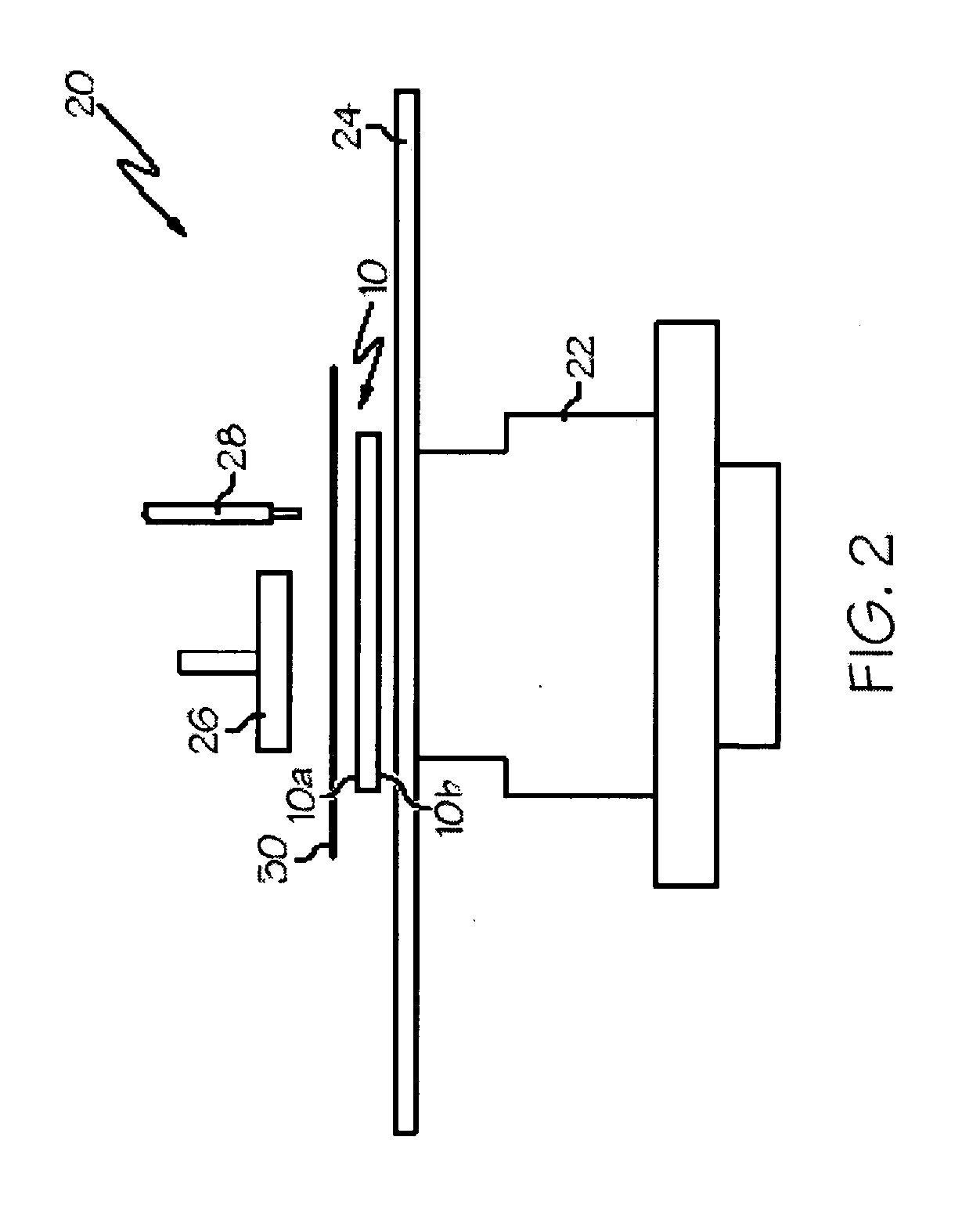
[0017] The present invention is also directed to a method of producing a mat as described above by printing a graphic image on the lower surface thereof. In one aspect of such a method, a screen printing device is used to print the graphic image on the lower surface of the mat (including the lip portion, if desired). In another aspect of the method, a backing layer, such as a layer of white ink, may be added to increase the visibility of the graphic image when the mat is in use.

Problems solved by technology

Further, such a structure provides increased opportunity for failure of the mat at specific points within the structure thereof.
For example, if either of the adhesive layers fails, the mat will come apart.

Method used


Image

  • Graphic mat and method of producing the same
  • Graphic mat and method of producing the same
  • Graphic mat and method of producing the same

Examples


Embodiment Construction

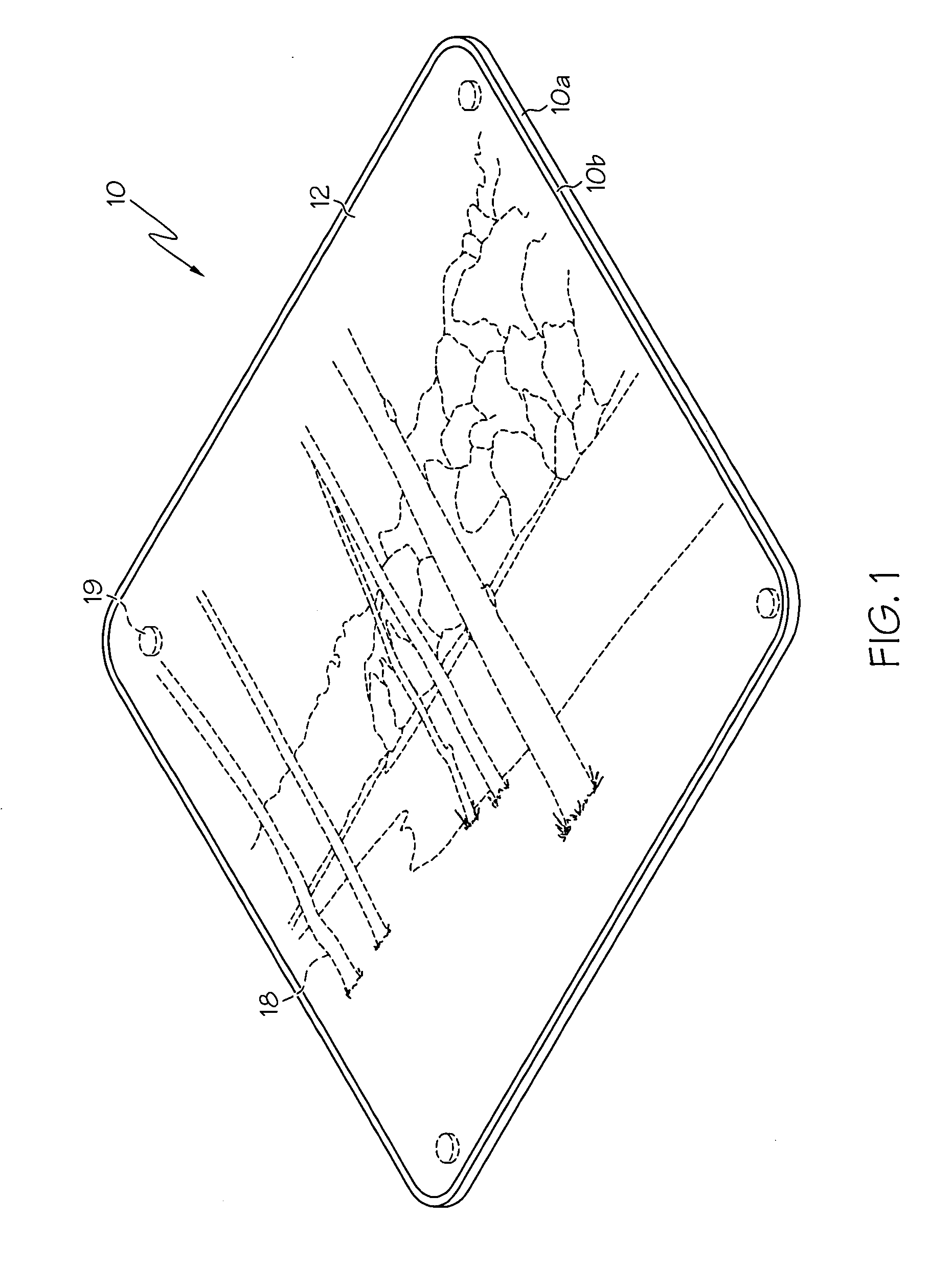
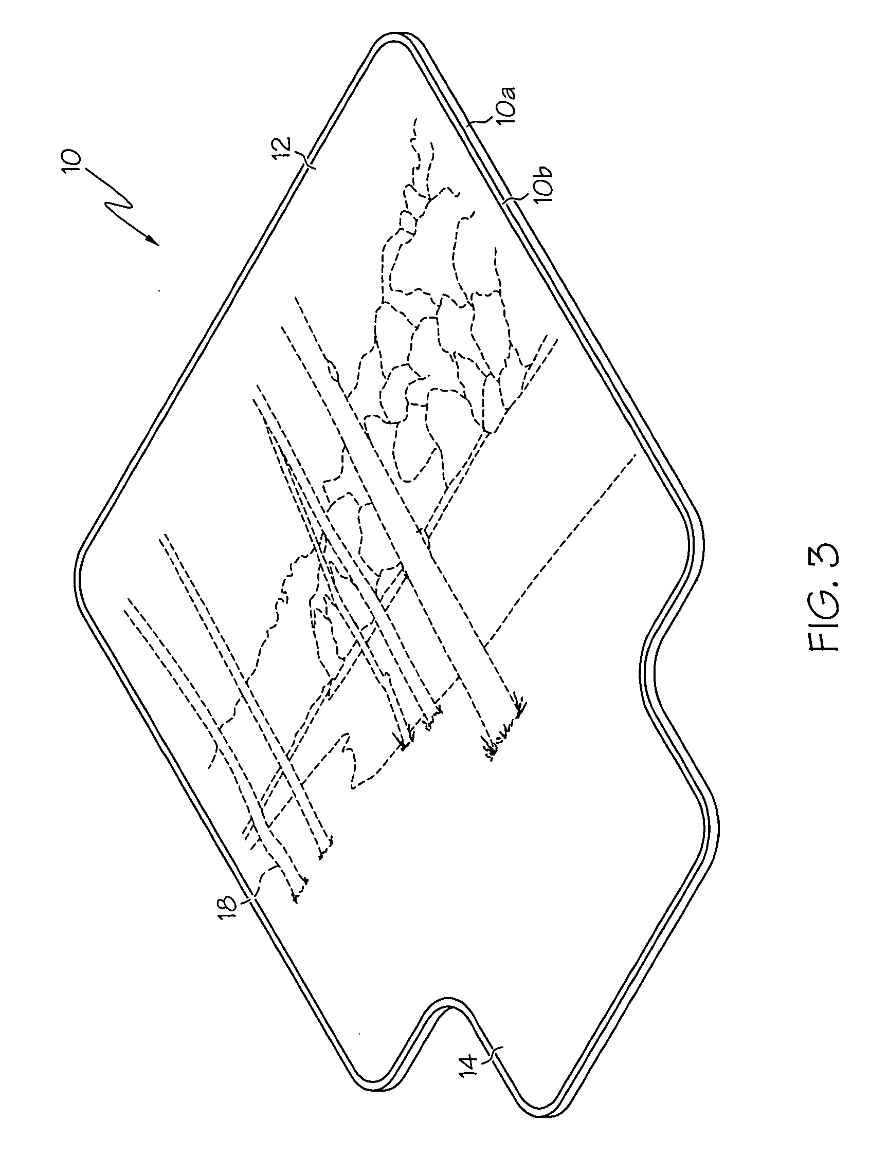
[0021] Turning now to the drawings, wherein like numerals indicate like parts, the numeral 10 refers generally to a protective mat constructed in accordance with the teachings of the present invention. FIG. 1 provides an illustration of a representative mat for use on a floor. The protective mat is presented in FIG. 1 such that a top or upper surface of the mat is facing ‘up’ and is visible in the figure. Protective mat 10 includes a body 12, which makes up the majority of the surface area of mat 10 and upon which a chair is able to move without damaging the floor beneath. Protective mat 10 also includes an upper surface 10b and an under surface 10a. Protective mat 10 further includes a graphic image 18 printed on under surface 10a thereof.

[0022] Protective mat 10 may further include at least one securing portion 19 in order to secure the protective mat to the surface upon which it rests. Any suitable method of securing protective mat 10 may be used, the nature of the surface upon ...


PUM


Abstract

The present invention is directed to a protective mat having a body portion with an upper and lower surface, and further having a graphic image printed on the lower surface of the body such that the image is visible through the upper surface of the mat. Another aspect of the present invention provides a backing to increase visibility of the graphic image when the protective mat is in use.

Description

CROSS-REFERENCE TO RELATED APPLICATIONS [0001] Not Applicable. STATEMENT REGARDING FEDERALLY SPONSORED RESEARCH OR DEVELOPMENT [0002] Not Applicable. INCORPORATION BY REFERENCE OF MATERIAL SUBMITTED ON A COMPACT DISC [0003] Not Applicable. BACKGROUND OF THE INVENTION [0004] 1. Field of the Invention [0005] The present invention relates generally to a protective mat and, more specifically, to a protective mat having a decorative graphic associated therewith. [0006] 2. Description of Related Art [0007] Protective mats are well-known in the art, and are commonly used in home and office settings as protective coverings for carpeting, hardwood floors, vinyl floors, furniture, or other surfaces. Such mats typically have a main body upon which a desk chair or other article is situated. The main body has a relatively hard, smooth surface upon which the chair is able to roll, and a forward lip portion that extends under a desk such that a person sitting in the chair can place his feet on the...

Claims


Application Information

Patent Timeline
Patent Type & Authority Applications(United States)
IPC IPC(8): G03G7/00
CPCB32B7/00G03G7/0026Y10T428/24802G03G8/00G03G7/0093A47G27/0206
Inventor R. DE ST. AUBIN, ART
Owner ROLITE PLASTICS
Learn More