
Flying toy with extending wings

a technology of extending wings and flying toys, which is applied in the field of flying toys, can solve the problems of large lifting, difficult to achieve the effect of induced drag from such a wing, and the performance of traditional toy gliders with fixed wings that are less than optimal,

Inactive Publication Date: 2006-11-30
MATTEL INC
View PDF99 Cites 27 Cited by
  • Summary
  • Abstract
  • Description
  • Claims
  • Application Information

AI Technical Summary

Benefits of technology

[0009] In one example, a flying toy may comprise an elongate body extending along a body axis from a forward end to a rearward end. The flying toy may comprise a wing assembly, which may comprise a wing adapted to pivot relative to the body between a retracted position in which at least a portion of the wing is proximate the body and an extended position in which the wing portion extends away from the body. The flying toy may comprise an actuator movable along the body from a forward position toward a rearward position. One of the wing assembly an

Problems solved by technology

However, traditional toy gliders with fixed wings may deliver less than optimal performance due to the drag imposed by the wing.
Toy gliders tend to have relatively large wings, which tend to create large amounts of lift.
While the large amounts of lift produced by the wings of a glider may be desirable during the gliding phase of flight, the induced drag from such a wing may be problematic during the launching phase.
However, the different conditions during the launch and glide phases of flight may make it difficult to improve both the launching and gliding performance of a fixed configuration glider.
However, large wings tend to produce significant amounts of aerodynamic drag, which would be detrimental to launching performance.

Method used


Image

  • Flying toy with extending wings
  • Flying toy with extending wings
  • Flying toy with extending wings

Examples


Embodiment Construction

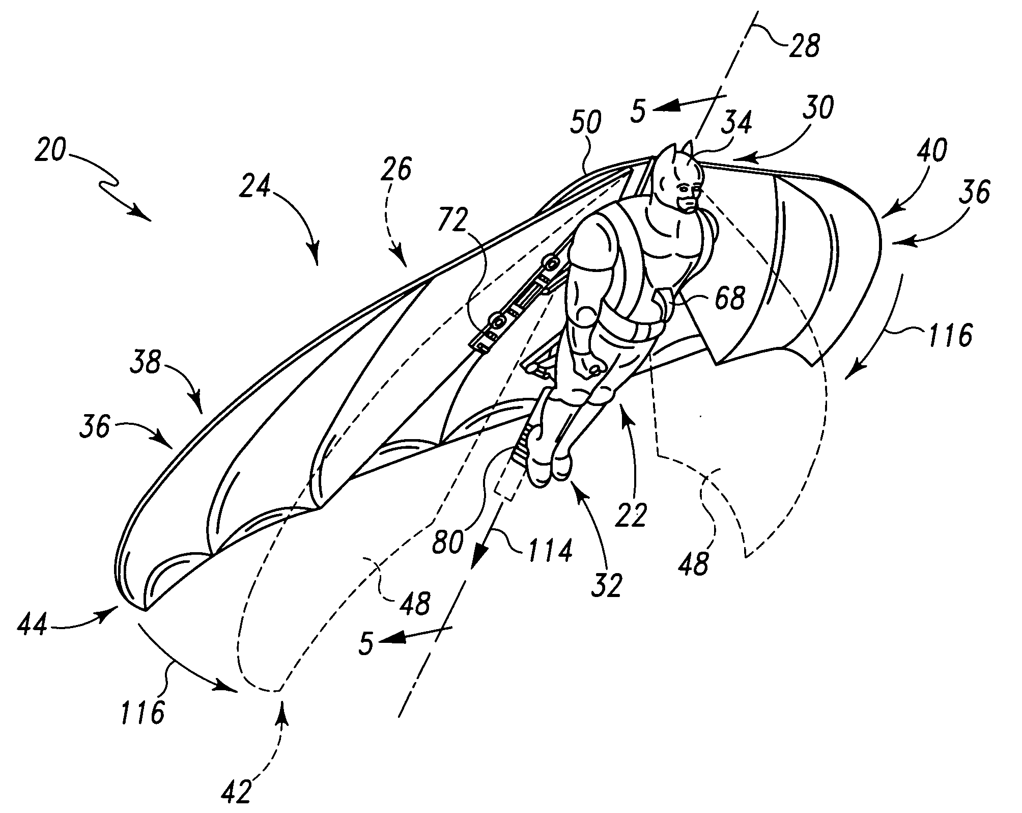
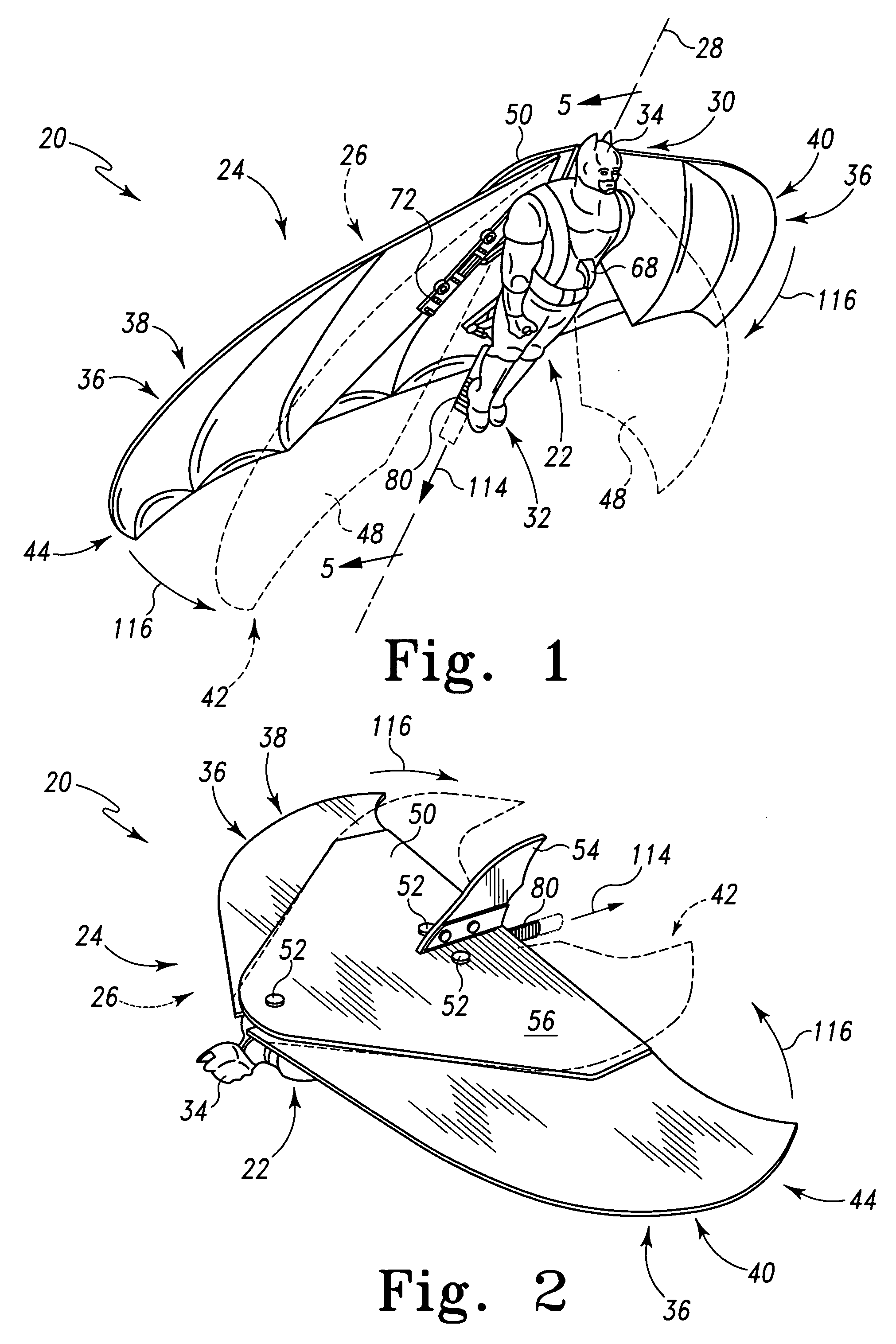
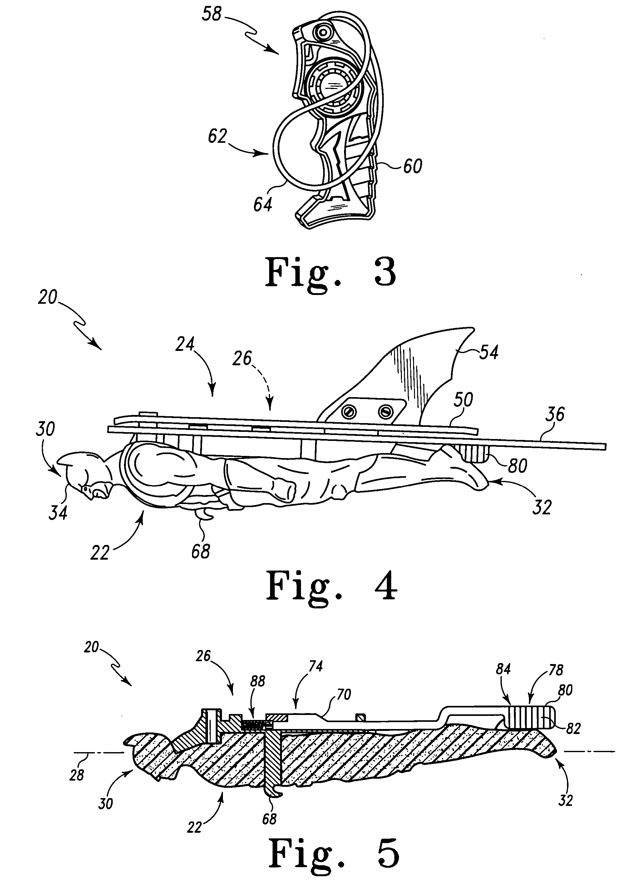
[0022] An illustrative example of a flying toy is shown generally at 20 in FIGS. 1-2. Flying toy 20 may include a body 22, a wing assembly 24, and a wing extension mechanism 26. As shown in the illustrative embodiment presented in FIG. 1, body 22 and wing assembly 24 may be mutually configured such that flying toy 20 is configured as a tailless aircraft.

[0023] Body 22 may be a generally elongate structure that extends along a body axis 28 from a forward end 30 to a rearward end 32. The external surfaces of body 22 may be configured into any suitable shape such as to resemble a human figure, an animal, an aircraft fuselage, or the like. As shown in the illustrative embodiment presented in FIG. 1, when body 22 is configured to resemble a human figure, forward end 30 may be configured to resemble a head, and rearward end 32 may be configured to resemble feet. In some embodiments, body 22 may be configured to resemble a superhero, such as the character BATMAN, as shown in FIG. 1. BATMA...


PUM


Abstract

A flying toy may comprise an elongate body extending along a body axis from a forward end to a rearward end. The flying toy may comprise a wing assembly, comprising a wing adapted to move relative to the body between an extended position in which at least a portion of the wing extends away from the body and a retracted position in which the wing portion is closer to the body. The flying toy may comprise an actuator movable along the body between a forward position and a rearward position. One of the wing assembly and the actuator may comprise a contact element, and the other of the wing assembly and the actuator may comprise an elongate contact surface extending obliquely relative to the body axis. The contact element may move along the contact surface as the actuator moves between the rearward position and the forward position, thereby moving the wing between the retracted position and the extended position.

Description

[0001] This application claims the benefit of U.S. Provisional Patent Application Ser. No. 60 / 685,166, filed May 27, 2005. The complete disclosure of the above-identified patent application is hereby incorporated by reference in its entirety for all purposes.FIELD OF THE DISCLOSURE [0002] The present disclosure relates generally to flying toys and, more particularly, to toy gliders having extending wings. Such flying toys may be launched with an elastic mechanism. BACKGROUND OF THE DISCLOSURE [0003] Flying toys are well known, including toy gliders launched with an elastic mechanism, such as a rubber band. However, traditional toy gliders with fixed wings may deliver less than optimal performance due to the drag imposed by the wing. Toy gliders tend to have relatively large wings, which tend to create large amounts of lift. While the large amounts of lift produced by the wings of a glider may be desirable during the gliding phase of flight, the induced drag from such a wing may be p...

Claims


Application Information

Patent Timeline
IPC IPC(8): A63H27/00A63H27/14F41B3/02
CPCA63H27/008F42B10/18F42B6/00F41B3/02
Inventor MONTALVO, MICHAELSTRAUSS, MICHAEL
Owner MATTEL INC
Learn More