Heel effect compensation filter X-ray irradiator, X-ray CT scanner and method for X-ray CT imaging

a filter and filter technology, applied in tomography, nuclear engineering, applications, etc., can solve the problems of overexposed body parts of examinees, excessive radiation amount, blurry slice data obtained by detecting the transmitted x-ray flux by the detector, etc., to achieve high effective energy, reduce unnecessary exposure of subjects, and achieve high effective energy

Inactive Publication Date: 2008-09-30
NAT INST OF RADIOLOGICAL SCI
View PDF9 Cites 30 Cited by
  • Summary
  • Abstract
  • Description
  • Claims
  • Application Information

AI Technical Summary

Benefits of technology

[0048]According to the heel effect compensation filter, the X-ray intensity angular distribution of the X-ray flux which is nonuniform due to the heel effect can be made uniform. In addition, according to the heel effect compensation filter, the effective energy can be made high and uniform in a predetermined direction.
[0049]According to the X-ray irradiator, the X-ray intensity angular distribution of the X-ray flux which is nonuniform due to the heel effect can be made uniform, and therefore, unnecessary exposure of the subject can be reduced. In addition, according to the X-ray irradiator, the effective energy can be made high and uniform in a predetermined direction.
[0050]According to the X-ray CT scanner, the X-ray intensity angular distribution of the X-ray flux which is nonuniform due to the heel effect can be made uniform, and therefore, unnecessary exposure of the subject can be reduced. In addition, according to the X-ray CT scanner, the effective energy can be made high and uniform in a predetermined direction. At the same time, the artifacts, especially a beam hardening artifact, can be reduced, and image quality of image data can be made uniform in the body axis direction.
[0051]According to the X-ray CT imaging method, the effective energy can be made high and uniform in a predetermined direction, at the same time, the artifacts, especially a beam hardening artifact, can be reduced, and image quality of image data can be made uniform in the body axis direction.

Problems solved by technology

As a result, at a portion with a strong X-ray irradiation intensity, the irradiation amount becomes excessively high, and the body part of the examinee is overexposed.
However, the overexposure due to this heel effect has not been taken into account, and a part of the slice data obtained by detecting the transmitted X-ray flux by the detector becomes blurry.
In addition, there is a problem of artifacts (obstructive shadow) which are always present in X-ray CT imaging.
Generation of artifacts lowers accuracy of diagnosis or the like on a subject based on slice image data.

Method used


Image

  • Heel effect compensation filter X-ray irradiator, X-ray CT scanner and method for X-ray CT imaging
  • Heel effect compensation filter X-ray irradiator, X-ray CT scanner and method for X-ray CT imaging
  • Heel effect compensation filter X-ray irradiator, X-ray CT scanner and method for X-ray CT imaging

Examples


first embodiment

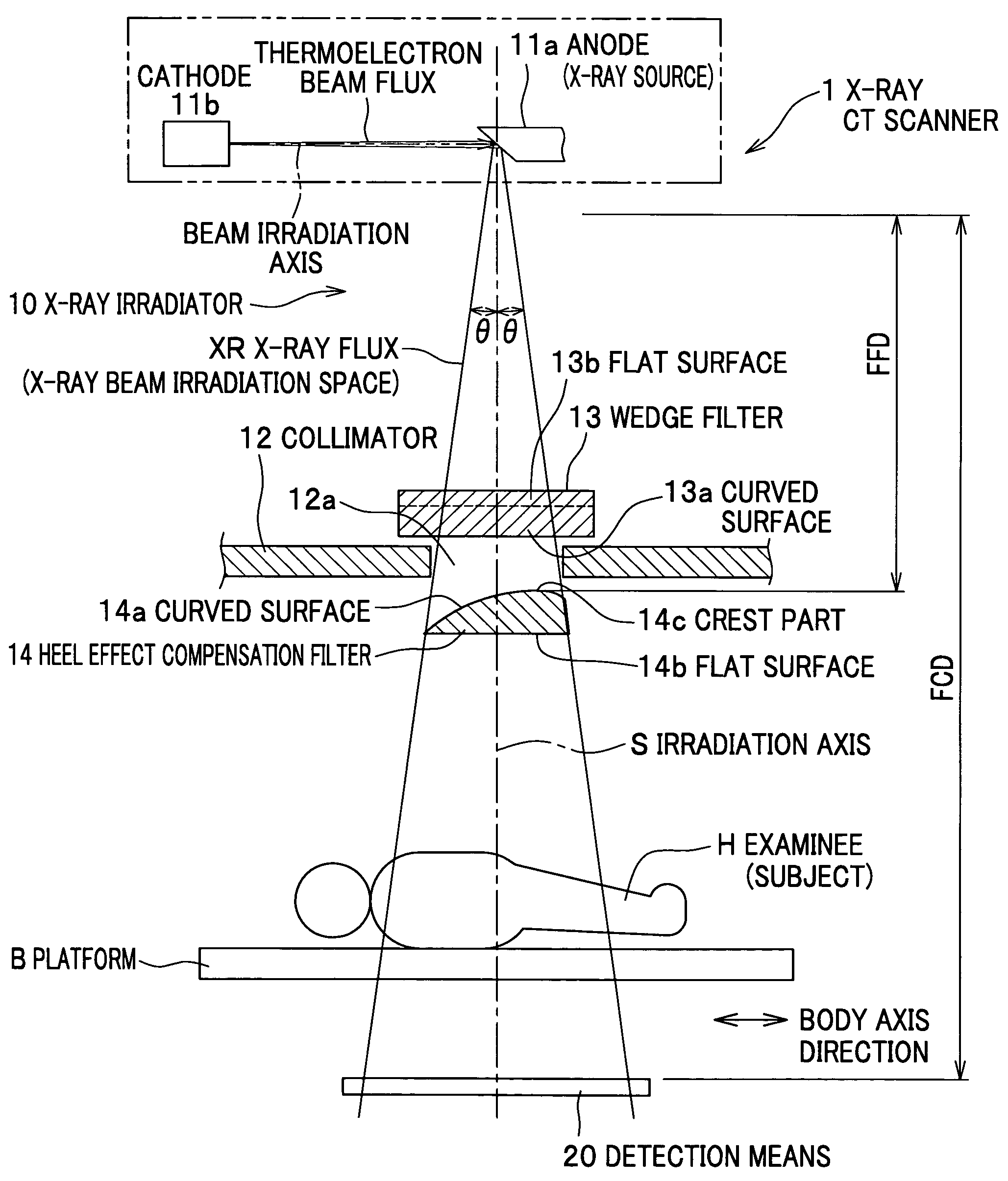
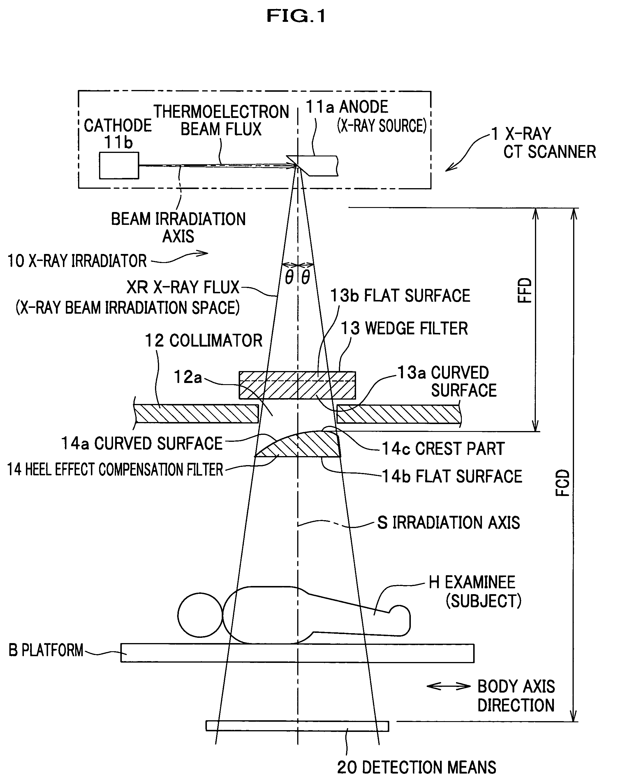
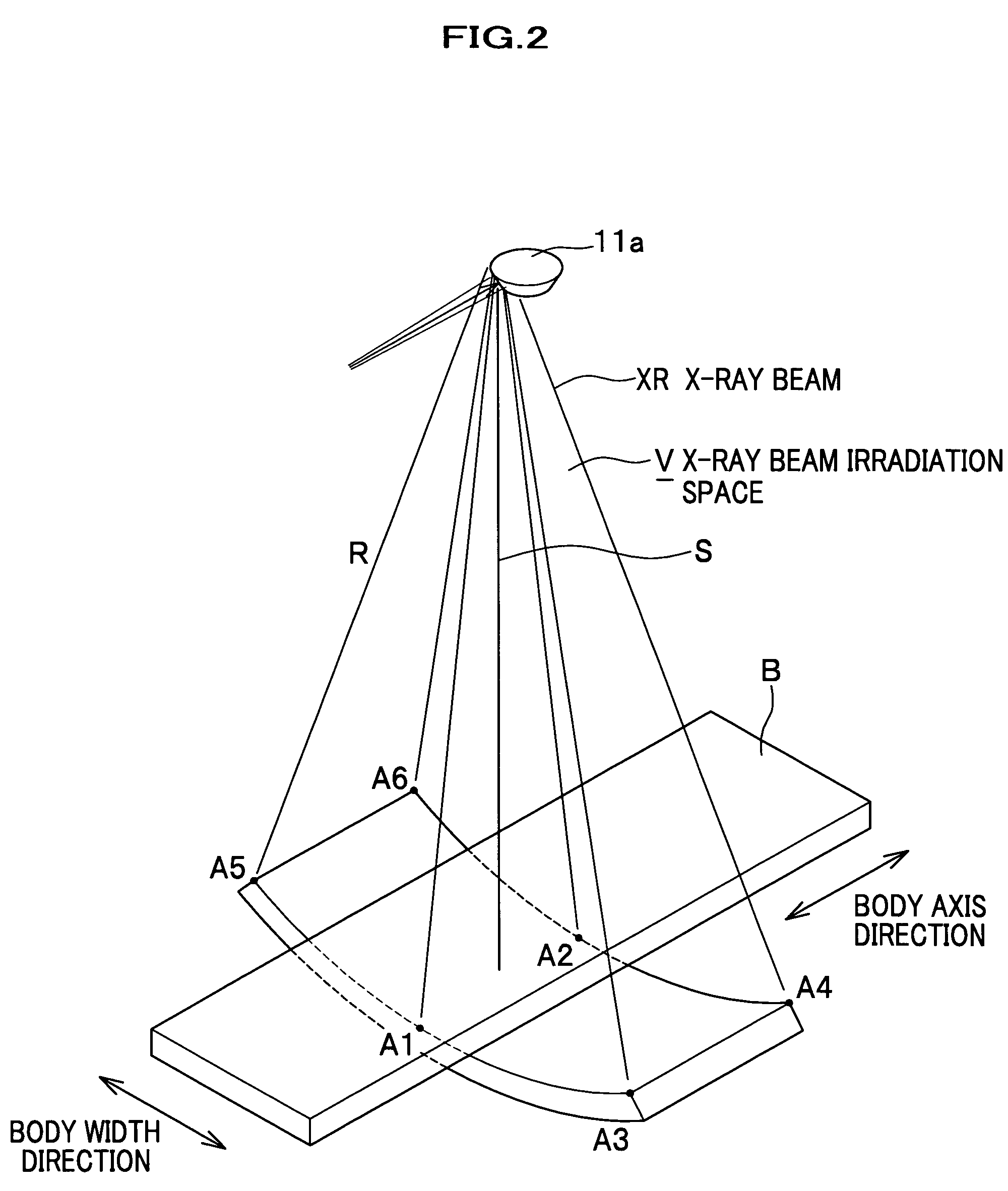
[0086]FIG. 1 is a plan view diagrammatically showing one example of X-ray irradiator according to a first embodiment of the present invention. FIG. 2 is a diagram showing one example of an X-ray flux irradiated space of the irradiated X-ray flux. FIG. 3(a) is a perspective view showing one example of a heel effect compensation filter, and (b) is a perspective view showing one example of a wedge filter. FIG. 4(a) is a diagram showing a case where a heel effect compensation filter is not used, (b) is an X-ray intensity map showing a case where the heel effect compensation filter is not used, (c) is a diagram showing a case where the heel effect compensation filter is used, and (d) is a graph of an X-ray intensity angular distribution showing a case where the heel effect compensation filter is used. FIG. 5 is a diagram showing a positional relationship of signs to be used in a formula. FIG. 6(a) is a diagram showing a maximum value and a minimum value of an X-ray intensity, and (b) is ...

second embodiment

[0144]An X-ray CT scanner according to a second embodiment of the present invention is different from the first embodiment in that, with respect to the X-ray irradiator 10a, a flat surface 14b of the heel effect compensation filter 14 as an X-ray flux XR-incoming side transmissive surface is formed on an X-ray source 11a side, and that a cylindrical convex surface 14a as an X-ray flux XR-outgoing side transmissive surface is formed on an examinee H-side, as shown in FIG. 8(a).

[0145]When a flat surface 14b of the heel effect compensation filter 14 is disposed between the collimator 12 and the examinee H at a position proximate to the collimator 12 and at a predetermined distance FFD away from the X-ray source 11a, the X-ray intensity angular distribution of the X-ray flux XR becomes uniform at a predetermined distance FCD away from the X-ray source 11a, continuously along a body axis direction in the X-ray flux irradiated space V.

[0146]Even when the heel effect compensation filter 14...

third embodiment

[0147]An X-ray CT scanner according to a third embodiment of the present invention is different from the first embodiment in that, with respect to the X-ray irradiator 10b, a flat surface 14b of the heel effect compensation filter 14 as an X-ray flux XR-incoming side transmissive surface is formed on an X-ray source 11a side, and that a cylindrical convex surface 14a as an X-ray flux XR-outgoing side transmissive surface is formed on an examinee H-side, and that the heel effect compensation filter 14 is disposed between the wedge filter 13 positioned on an X-ray source 11a side and the collimator 12, as shown in FIG. 8(c).

[0148]Even when the heel effect compensation filter 14 is placed as explained above, like the first embodiment, as shown in FIG. 8(d), at a predetermined distance FCD from the X-ray source 11a (by the detection means 20), the X-ray intensity angular distribution of the X-ray flux XR can be made uniform, and the examinee H is prevented from being unnecessarily expos...


PUM


Abstract

A heel effect compensation filter is configured to have a thickness distribution that uniforms an X-ray intensity angular distribution that is nonuniform in the body axis direction of a subject in an X-ray flux irradiated space. The space is formed by an X-ray flux diverging from an anode in a body width direction of the subject and diverging in a shape of an approximate sector in the body axis direction due to the heel effect, when the X-ray flux generated on the anode by irradiating a thermoelectron beam flux from a cathode to the anode is irradiated on the subject. The thickness distribution can be obtained using a predetermined formula.

Description

FIELD OF THE INVENTION[0001]The present invention relates to a heel effect compensation filter, an X-ray irradiator and an X-ray CT scanner, which adjust a nonuniform X-ray intensity angular distribution of an X-ray flux due to a heel effect to become uniform when the X-ray flux is irradiated on a subject. The present invention also relates to a heel effect compensation filter, an X-ray irradiator, an X-ray CT scanner and an X-ray CT imaging method, with which image quality of image data obtained with the X-ray CT scanner is made uniform and improved in a body axis direction.BACKGROUND ART[0002]An X-ray generator in general is a device which irradiates a thermoelectron beam flux from a cathode to an anode, and generates an X-ray flux at the anode. The X-ray flux generated by the X-ray generator is irradiated on a subject, and the X-ray flux transmitted through the subject is detected by a predetermined detection means, to thereby obtain information of a part through which the X-ray ...

Claims


Application Information

Patent Timeline
Patent Type & Authority Patents(United States)
IPC IPC(8): G21K3/00A61B6/03
CPCA61B6/032G21K1/10A61B6/4042A61B6/583
Inventor MORI, SHINICHIROUENDO, MASAHIRO
Owner NAT INST OF RADIOLOGICAL SCI
Why Eureka
Try Eureka