Method and apparatus for in-flight calibration of gyroscope using magnetometer reference

a gyroscope and magnetometer technology, applied in the field of guidance systems, can solve the problems of gyroscope area key expense in precision-guided weapons, gyroscope area is generally too small to generate significant lift, and devices meeting the scale factor and bias requirements of typical guidance systems cost thousands of dollars

Active Publication Date: 2011-07-14
BAE SYST INFORMATION & ELECTRONICS SYST INTERGRATION INC
View PDF14 Cites 31 Cited by
  • Summary
  • Abstract
  • Description
  • Claims
  • Application Information

AI Technical Summary

Problems solved by technology

The wings are generally too small to generate significant lift themselves.
Gyroscopes area key expense in precision-guided weapons.
Devices meeting the scale factor and bias requirements of typical guidance systems cost thousands of dollars.
Less expensive devices are known in the industry, but these devices have temperature sensitive scale factor and

Method used


Image

  • Method and apparatus for in-flight calibration of gyroscope using magnetometer reference
  • Method and apparatus for in-flight calibration of gyroscope using magnetometer reference
  • Method and apparatus for in-flight calibration of gyroscope using magnetometer reference

Examples


Embodiment Construction

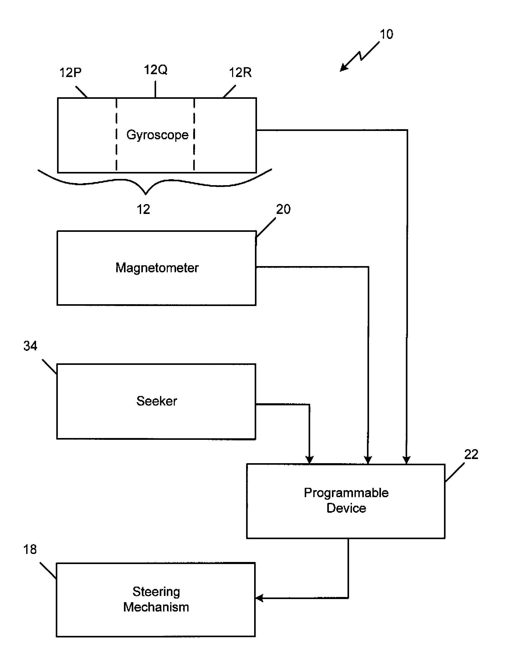
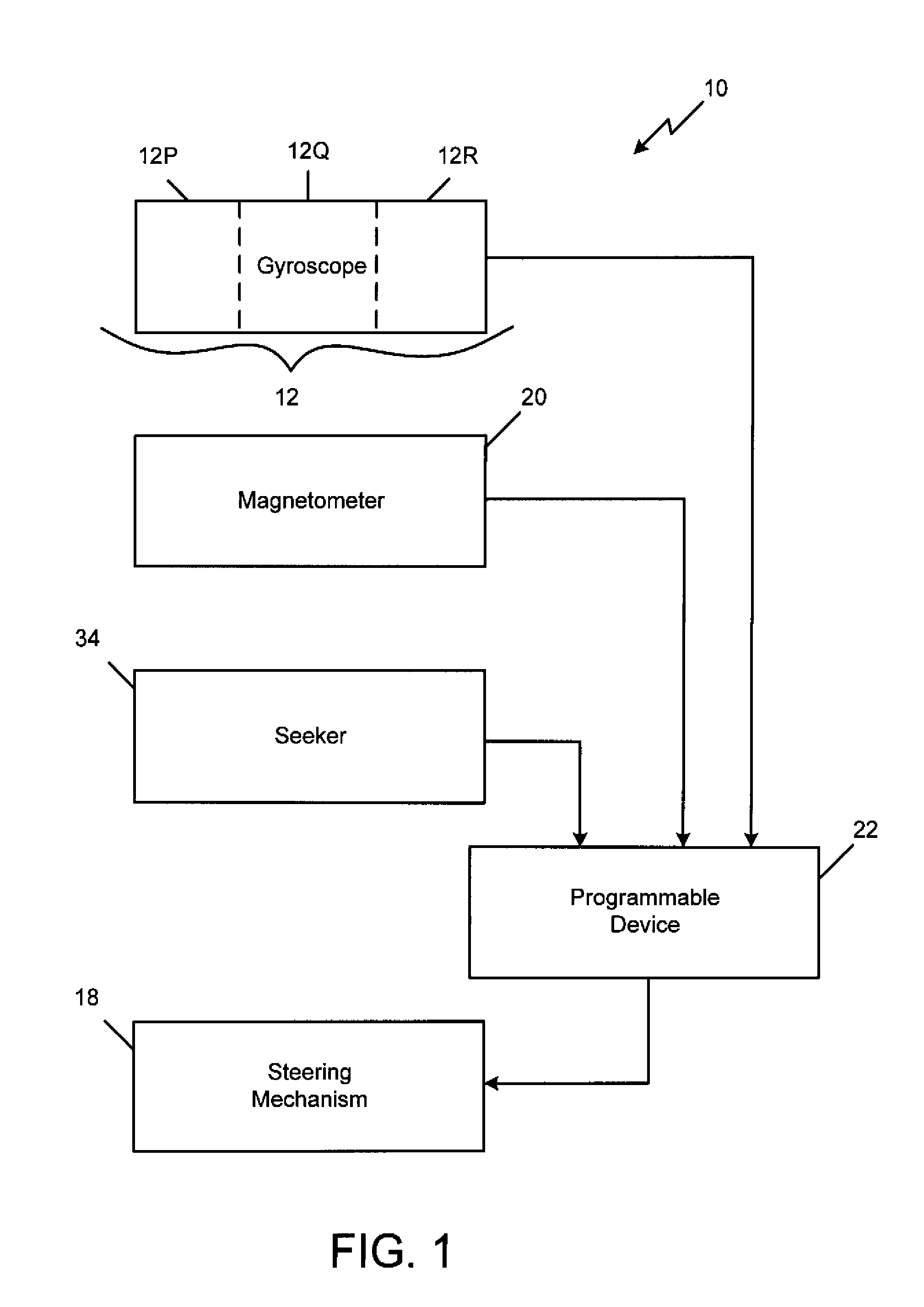
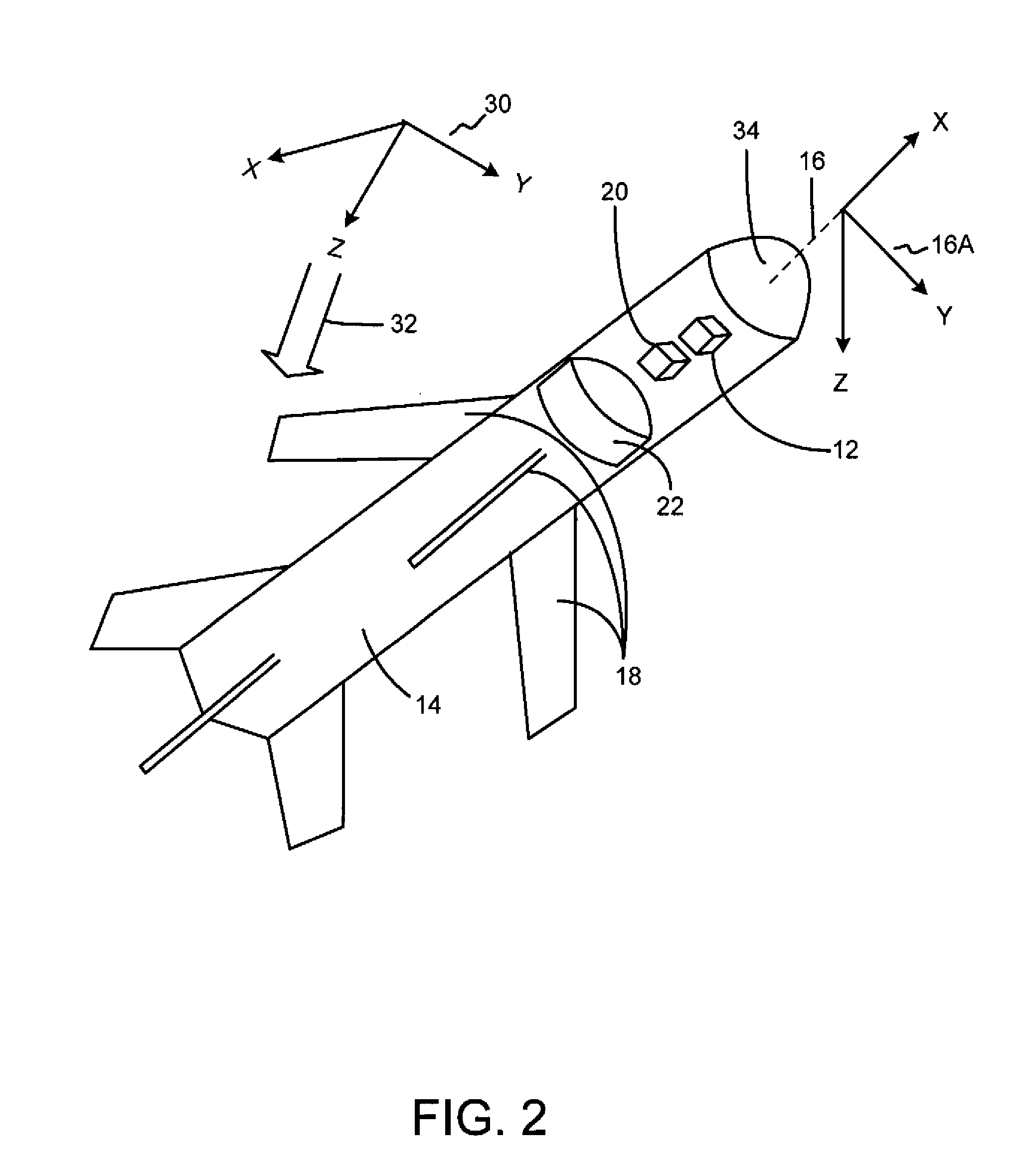
[0015]FIG. 1 is an illustration of a block diagram of a system 10 for calibrating a gyroscope 12, in accordance with a first exemplary embodiment of the present invention. FIG. 2 is a schematic diagram illustrating a cross-sectional view of projectile, in accordance with the first exemplary embodiment of the present invention. The system 10 includes a mobile vessel 14 having a body axis 16 and a steering mechanism 18. A three-axis gyroscope 12 is mounted within the vessel 14. A three-axis magnetometer 20 is mounted within the vessel 14 at a known relative orientation to the gyroscope. A seeker 34 is mounted to the vessel at a known orientation relative to the gyroscope. A programmable device 22 communicates with the three-axis gyroscope 12, the three-axis magnetometer 20, seeker 34, and the steering mechanism 18.

[0016]The mobile vessel 14 is initially conceived to be an airborne projectile, more specifically, a missile. The mobile vessel 14 may also be a torpedo or other water-based...


PUM


Abstract

The system includes a mobile vessel having a body axis and a steering mechanism. A three-axis gyroscope is mounted within the vessel. A three-axis magnetometer is mounted within the vessel. A programmable device communicates with the three-axis gyroscope, the three-axis magnetometer, and the steering mechanism. The three-axis gyroscope may include three single axis gyroscopes.

Description

STATEMENT OF GOVERNMENT INTEREST[0001]The invention was made with United States Government support under Contract No. HR0011-05-C-0577. The United States Government has certain rights in this invention.FIELD OF THE INVENTION[0002]The present invention is generally related to guidance systems, and more particularly, is related to a method and apparatus for in-flight calibration of gyroscope using magnetometer reference.BACKGROUND OF THE INVENTION[0003]Munitions guidance is typically implemented with proportional navigation. Assuming that both the target and guided system are moving in straight lines with constant velocity, the two systems will collide if the angle between the guided system velocity vector and the vector pointing to the target remains constant with time. Of course, neither the target nor the guided system remains at a constant velocity or direction. This is why the guidance solution is a closed loop control with continuous updates to impact.[0004]Munitions generally d...

Claims


Application Information

Patent Timeline
IPC IPC(8): G01C25/00
CPCF41G7/007G01C25/005G01C21/165G01C21/1654
Inventor FREY, JR., ROBERT D.
Owner BAE SYST INFORMATION & ELECTRONICS SYST INTERGRATION INC
Why Eureka
Try Eureka