Magnetic Resonance Imaging Apparatus

a magnetic resonance imaging and apparatus technology, applied in the field of magnetic resonance imaging apparatus, can solve problems such as image deterioration s/n, and achieve the effect of increasing the number of channels and reducing the electromagnetic coupling

Active Publication Date: 2011-02-10
HITACHI LTD
View PDF8 Cites 31 Cited by
  • Summary
  • Abstract
  • Description
  • Claims
  • Application Information

AI Technical Summary

Benefits of technology

[0011]However, the coil arrangement as described in the patent document 1 and the patent document 2 has a restriction in arranging the sub-coils when a total body is imaged. By way of example, if multiple coils are arranged in the body axis direction of the subject, additional modification is necessary for the coil arrangement described in the patent document 1, due to a structural restriction. When the coils are implemented across the total body according to the arrangement described in the patent document 2, a large number of auxiliary coils may be necessary in order to reduce the electromagnetic coupling between the opposed sub-coils. In other words, modifications of the above coil arrangement to achieve a total-body use arrangement may bring about the possibility of increase in the number of channels.

Problems solved by technology

If there exists electromagnetic coupling between the sub-coils, noise interference may occur between the coils, and this may deteriorate an image S / N.

Method used


Image

  • Magnetic Resonance Imaging Apparatus
  • Magnetic Resonance Imaging Apparatus
  • Magnetic Resonance Imaging Apparatus

Examples


first embodiment

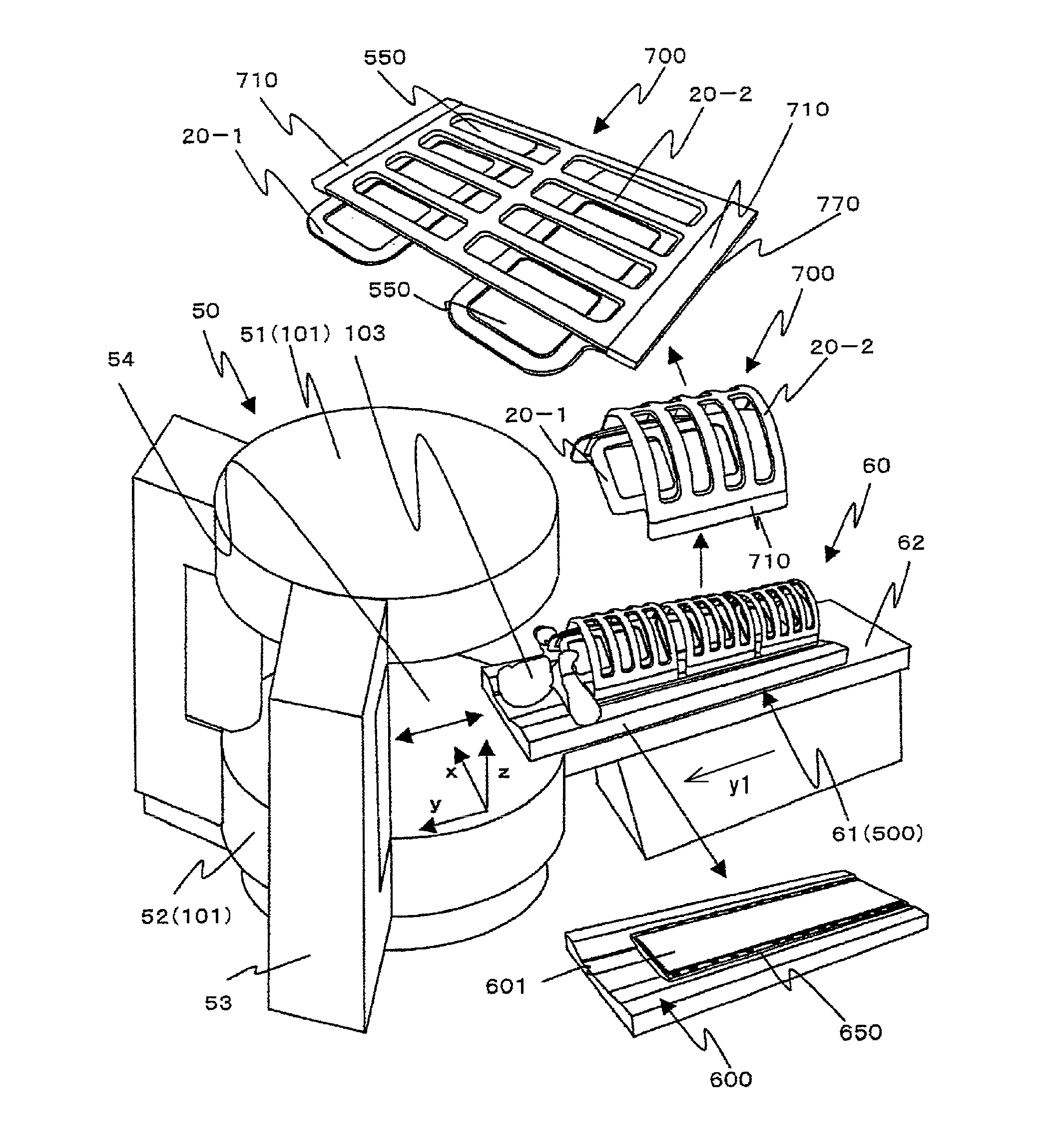
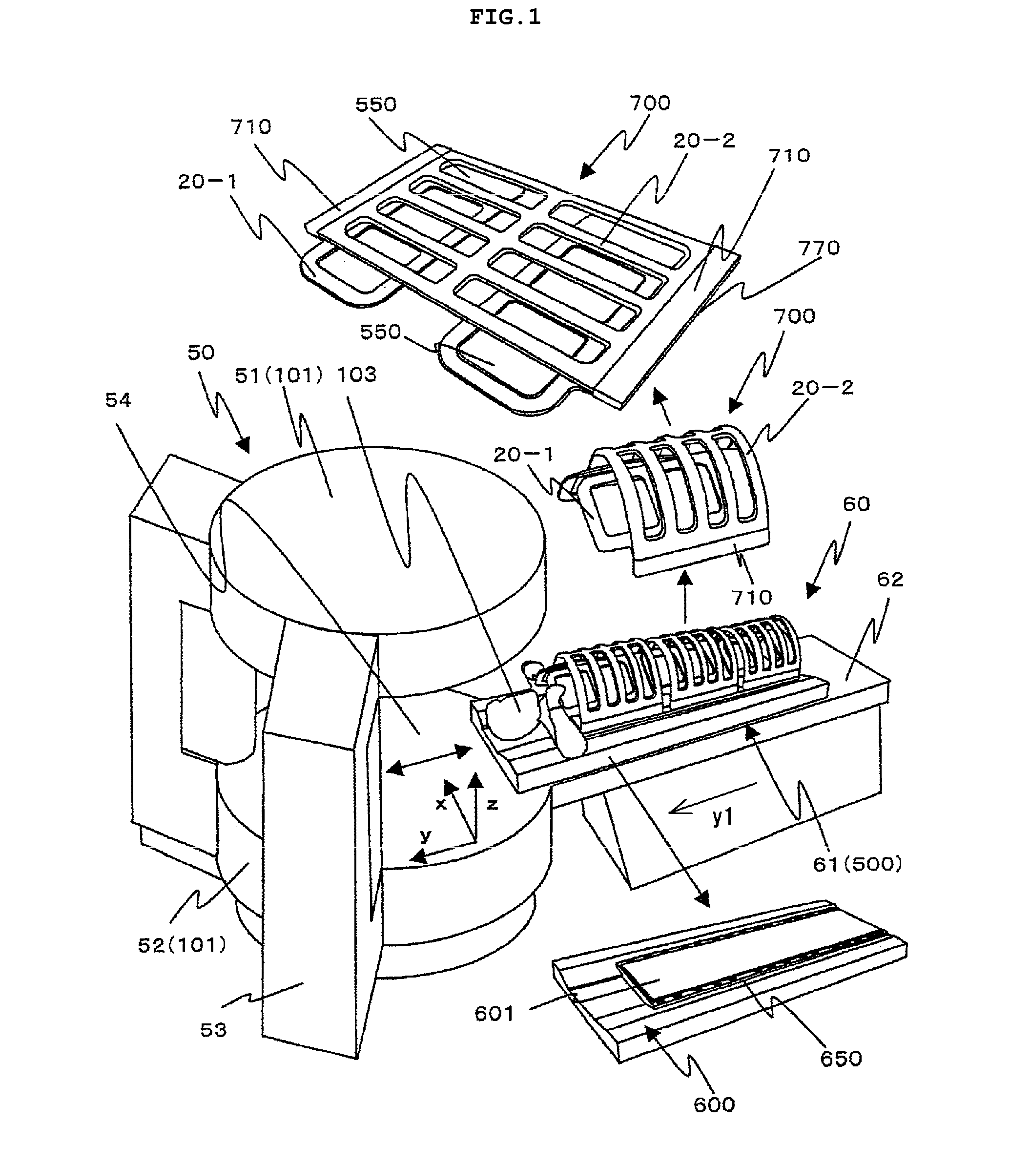
[0015]Initially, with reference to FIG. 1, a schematic structure of the MRI apparatus according to the present embodiment will be explained. FIG. 1 illustrates a schematic structure of the MRI apparatus.

[0016]In FIG. 1, the MRI apparatus according to the present embodiment comprises an MRI apparatus main unit 50 provided with a pair of magnets 101 placed above and below for generating a static magnetic field in the vertical direction z indicated by arrow z, a bed part 60 for inserting a subject (test object 103) into the static magnetic field in the vertical direction z of the MRI apparatus main unit 50, and other elements not illustrated, such as a power supply unit, a computer for processing images and the like.

[0017]The MRI apparatus main unit 50 is provided with an upper main body 51 and a lower main body 52 incorporating the magnets 101, and a support part 53 on the upper part of the lower main body 52, for connecting and supporting the upper main body 51. There is formed space...

second embodiment

[0112]Next, with reference to FIG. 30, an explanation will be made regarding an external configuration of the receiver coil unit according to the second embodiment. FIG. 30 illustrates the second embodiment, and FIG. 30(A) is a perspective view when a test object is set, FIG. 30(B) is a cross sectional view on a plane perpendicular to the body axis, FIG. 30(C) is a perspective view in the state where an outer support is open, and FIG. 30(D) is an external view when an inner support is open.

[0113]As illustrated, also in the present embodiment, a support for supporting a coil conductor has a dual structure made up of the outer support 20-2 and the inner support 20-1. As shown in FIG. 30(C), the outer support 20-2 has a structure that is dividable into the back side and chest side of the subject, and it is openable at one side of the test object 103. As shown in FIG. 30(D), the inner support 20-1 is openable from the upper side of the test object 103 (the ventral side of human being pl...


PUM


Abstract

The present invention provides a vertical magnetic field MRI apparatus which is capable of speeding up imaging for taking an image of any cross section of a wide area such as a total body, while suppressing increase of the number of channels and maintaining high sensitivity in a deep portion of a subject. A receiver coil unit 500 incorporates a bed coil unit 600 whose longitudinal direction agrees with a body axis direction of the test object 103, and an upper coil unit 700 which is detachably mounted on the bed coil unit 600. The bed coil unit 600 is provided with a carrying surface 601 for placing the test object 103 thereon and multiple lower sub-coils arranged in a lower part of the carrying surface 601, and the upper coil unit 700 is provided with multiple upper sub-coils which are connected to the lower sub-coils. The upper sub-coils are separated into two parts; one arranged in a flexible inner support 20-1 covering the installation surface 601 and another arranged in a flexible outer support 20-2 covering the external side of the inner support 20-1. The upper sub-coils and the lower sub-coils are connected by mounting the upper coil unit 700 on the bed coil unit 600, thereby forming the multiple types of sub-coils.

Description

TECHNICAL FIELD[0001]The present invention relates to a magnetic resonance imaging apparatus (MRI apparatus), and in particular, it relates to an vertical magnetic field type MRI apparatus, and an RF receiver coil for detecting a nuclear magnetic resonance signal which is suitable for the vertical magnetic field type MRI apparatus.BACKGROUND ART[0002]In the MRI apparatus, a test object is placed in homogeneous static magnetic field space, and imaging of the test object is performed by using nuclear magnetic resonance. An imaging region is limited to the static magnetic field space. In recent years, a method for imaging a total body has been developed, which moves a table (bed) on which the test object is placed, and now attention is particularly given to attempts of a total body screening by use of the MRI.[0003]When measurement is performed as to a wide area such as the total body, it is desired to implement a receiver coil which is able to keep high sensitivity across the wide are...

Claims


Application Information

Patent Timeline
Patent Type & Authority Applications(United States)
IPC IPC(8): G01R33/34
CPCA61B5/055G01R33/3415G01R33/34084G01R33/34007A61B5/704
Inventor NINOMIYA, ATSUSHIKASAI, YOSHIMIOCHI, HISAAKIDOHATA, MASAYOSHIMIYAMOTO, YOSHIYUKINAGAI, SHIZUKA
Owner HITACHI LTD
Why Eureka
Try Eureka