Eureka AIR delivers breakthrough ideas for toughest innovation challenges, trusted by R&D personnel around the world.

Passive mixer driven power amplification device and nonlinear compensation method

A passive mixer and frequency mixing technology, which is applied in the field of communication, can solve problems such as poor port isolation, signal amplitude changes, and lack of isolation.

Active Publication Date: 2018-07-06
WUXI ZGMICRO ELECTRONICS CO LTD
View PDF5 Cites 2 Cited by
  • Summary
  • Abstract
  • Description
  • Claims
  • Application Information

AI Technical Summary

Problems solved by technology

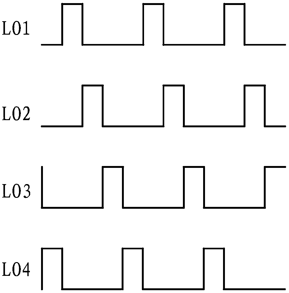
[0003] Passive mixers also have some disadvantages, notably poor isolation between the different ports, and a 25% duty cycle LO local oscillator clock signal is used to eliminate the interaction of the I and Q signal paths
However, at the special moment when the switch of the mixer is turned on, there is basically no isolation between the radio frequency RF and the intermediate frequency IF
At this time, the analog circuit before the mixer must directly drive the input capacitor of a large power amplifier, and the voltage on the capacitor cannot completely follow the input baseband signal, which causes the amplitude of the signal to change with the I and Q changes of the baseband

Method used


Image

  • Passive mixer driven power amplification device and nonlinear compensation method
  • Passive mixer driven power amplification device and nonlinear compensation method
  • Passive mixer driven power amplification device and nonlinear compensation method

Examples


Embodiment Construction

[0020] In order to express the technical solutions and advantages of the embodiments of the present invention more clearly, the technical solutions of the present invention will be further described in detail below with reference to the drawings and embodiments.

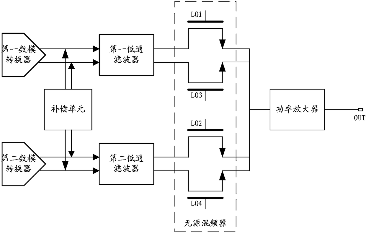
[0021] figure 1 It is a circuit diagram of a power amplifier device driven by a passive mixer according to an embodiment of the present invention. Such as figure 1 As shown, the first embodiment of the present invention proposes a passive mixer driving power amplifier device, which mainly includes: a first digital-to-analog converter, a first low-pass filter, a second digital-to-analog converter, a second low-pass Filters, compensation units, passive mixers and power amplifiers.

[0022] The connection mode of the device is: the output end of the first digital-to-analog converter is connected to the input end of the first low-pass filter, and the output end of the first low-pass filter is connected to the first inp...


PUM


Abstract

The invention relates to a passive mixer driven power amplification device and a nonlinear compensation method, wherein the passive mixer driven power amplification device comprises a first digital-to-analog converter, a first low-pass filter, a second digital-to-analog converter, a second low-pass filter, a power amplifier, a compensation unit and a passive mixer, wherein an output end of the first digital-to-analog converter is connected with an input end of the first low-pass filter, and the output end of the first low-pass filter is connected with a first input end of the passive mixer; the output end of the second digital-to-analog converter is connected with the input end of the second low-pass filter, and the output end of the second low-pass filter is connected with a second inputend of the passive mixer; the output end of the passive mixer is connected with the input end of the power amplifier; the compensation unit is used for injecting a baseband harmonic compensation signal with preset frequency, phase and amplitude into a baseband signal; the passive mixer is used for performing frequency mixing for the baseband signal comprising the baseband harmonic compensation signal, and a local oscillation signal to obtain a radio frequency signal; and the radio frequency signal is output after being amplified through the power amplifier.

Description

technical field [0001] The invention relates to the field of communication technology, in particular to a passive mixer driving power amplifier device and a nonlinear compensation method. Background technique [0002] In wireless transmitters, passive mixers have some advantages over active mixers. In theory, passive mixers do not consume DC power consumption. They work in the voltage domain and directly drive the power amplifier behind them, unlike conventional Inductive loads are required like source mixers. This avoids electromagnetic coupling between the mixer and the voltage controlled oscillator via passive loads. [0003] Passive mixers also have some disadvantages, notably poor isolation between the different ports, and a 25% duty cycle LO local oscillator clock signal is used to eliminate interaction between the I and Q signal paths. However, at the special moment when the switch of the mixer is turned on, there is basically no isolation between the radio frequenc...

Claims


Application Information

Patent Timeline
IPC IPC(8): H04B1/04H03D7/16H03D7/14
CPCH03D7/1466H03D7/16H04B1/04H04B2001/0425H04B2001/0491
Inventor 李明原吴悦
Owner WUXI ZGMICRO ELECTRONICS CO LTD
Why Eureka
Eureka Blog
Learn More