Stent delivery guide wire

a technology of guide wires and stents, applied in the field of guide wires and catheters, can solve the problems of increased difficulty in controlling, increased wall contact, and potential trauma to the vessel, and achieve the effects of improving the safety of patients

Active Publication Date: 2006-11-30
STEREOTAXIS
View PDF10 Cites 53 Cited by
  • Summary
  • Abstract
  • Description
  • Claims
  • Application Information

AI Technical Summary

Benefits of technology

This patent describes how to make a special guide wire for use in medical procedures. The guide wire has two parts: a flexible part at the front (which helps with navigation through narrow spaces) and a stiffer back part where most of the control over movement takes place. Both parts have small magnets attached to them, allowing the doctor to move the wire around inside the patient's body without it bending too much. The new feature added to this design are some tapering of the flexible front part - this makes the wire easier to maneuver while keeping it strong enough to support other tools used during surgery.

Problems solved by technology

The technical problem addressed in this patent text is the difficulty of negotiating the sharp turns required to reach the target area for delivery of medical therapy using conventional guide wires. After several bends, it becomes increasingly difficult to control the guide wire and guide a therapeutic device to the same location. To address this problem, magnetically navigable guide wires and balloon catheters have been developed which can be controlled with an external magnetic field. However, the added stiffness of carrying a stent can make navigation more difficult with existing magnetic guidewires.

Method used


Image

  • Stent delivery guide wire
  • Stent delivery guide wire
  • Stent delivery guide wire

Examples


Embodiment Construction

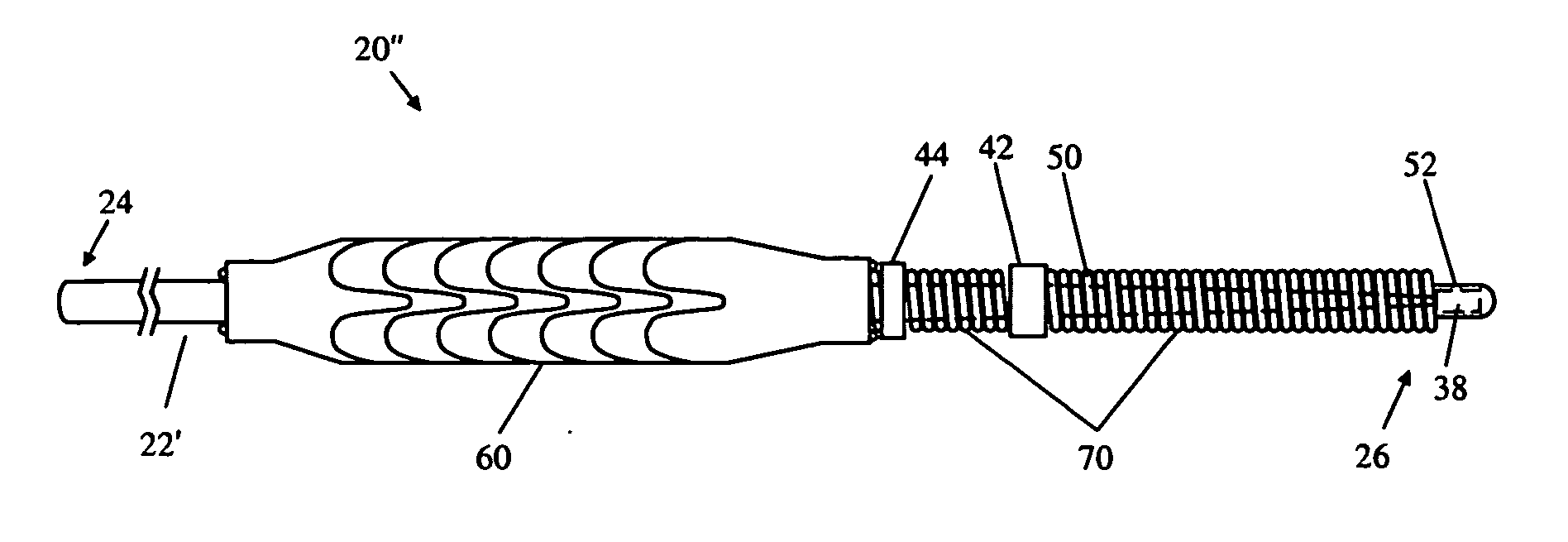
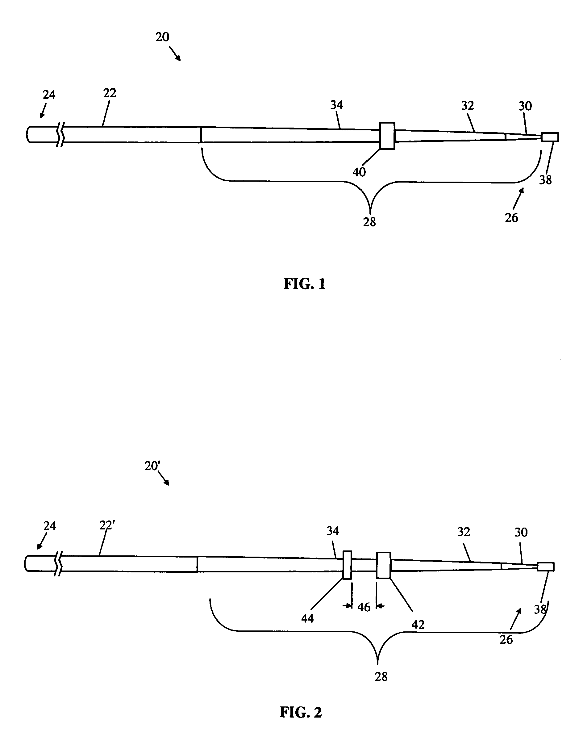
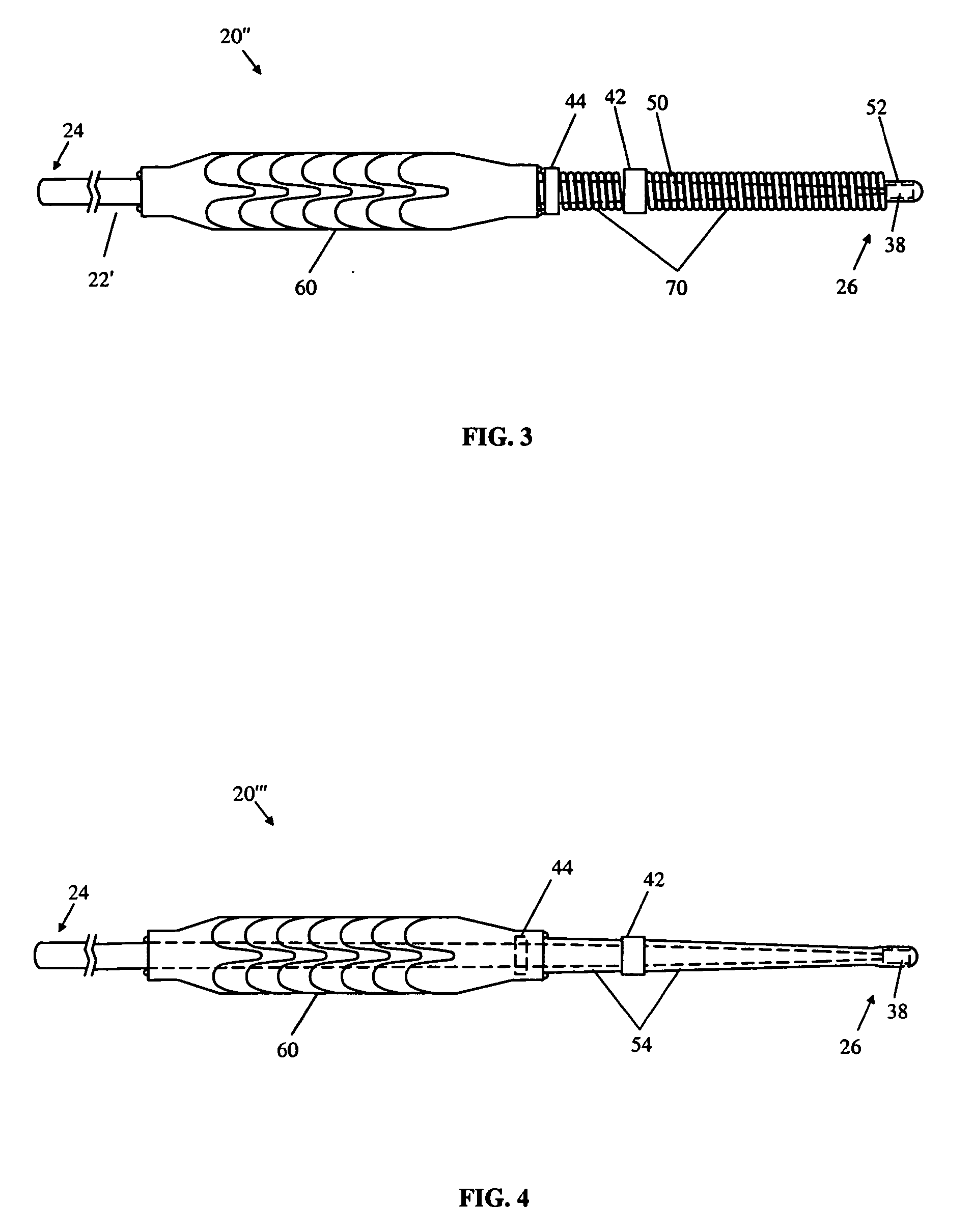
[0019] A preferred embodiment of magnetically navigable guide wire in accordance with the principles of the present invention is indicated generally as 20 in FIG. 1. The guide wire 20 comprises an elongate wire 22 having a proximal end 24, a distal end 26. A portion 28 of the wire 22 adjacent the distal end is more flexible than the more proximal portions of the elongate wire. The elongate wire 22 is preferably made of a memory shaped superelastic alloys, such as nickel-titanium (nitinol), stainless steel, or other suitable flexible, biocompatible material.

[0020] In the preferred embodiment of the present invention shown in FIG. 1, the more flexible portion 28 at the distal end 26 of the elongate wire 22 may comprise one or more tapered sections 30, 32 and 34, which decrease in diameter toward their distal ends. This decrease in diameter can be uniform or non-uniform over each section. In this preferred embodiment, the most proximal section 34 tapers from a diameter of about 0.325 ...


PUM


Abstract

A guide wire for magnetically navigating a medical device through in a subject's body comprising an elongate wire having a proximal and distal end, a portion adjacent the distal end that is more flexible than the more proximal portions of the elongate wire, and a first magnetically responsive element on the distal end of the elongate wire. The guide wire further comprises one or more magnetically responsive elements spaced apart from the first magnetically responsive element and disposed on the more flexible portion of the elongate wire. The guide wire provides for bending or deflecting the distal end of the stent, to provide easier navigation of the distal end of the guide wire and the stent through the vasculature of a subject body.

Description


Claims


Application Information

Patent Timeline
Owner STEREOTAXIS
Why Eureka
Try Eureka