
Retrievable downhole tool and running tool

Active Publication Date: 2006-12-07
SCHLUMBERGER TECH CORP
View PDF15 Cites 39 Cited by
  • Summary
  • Abstract
  • Description
  • Claims
  • Application Information

AI Technical Summary

Benefits of technology

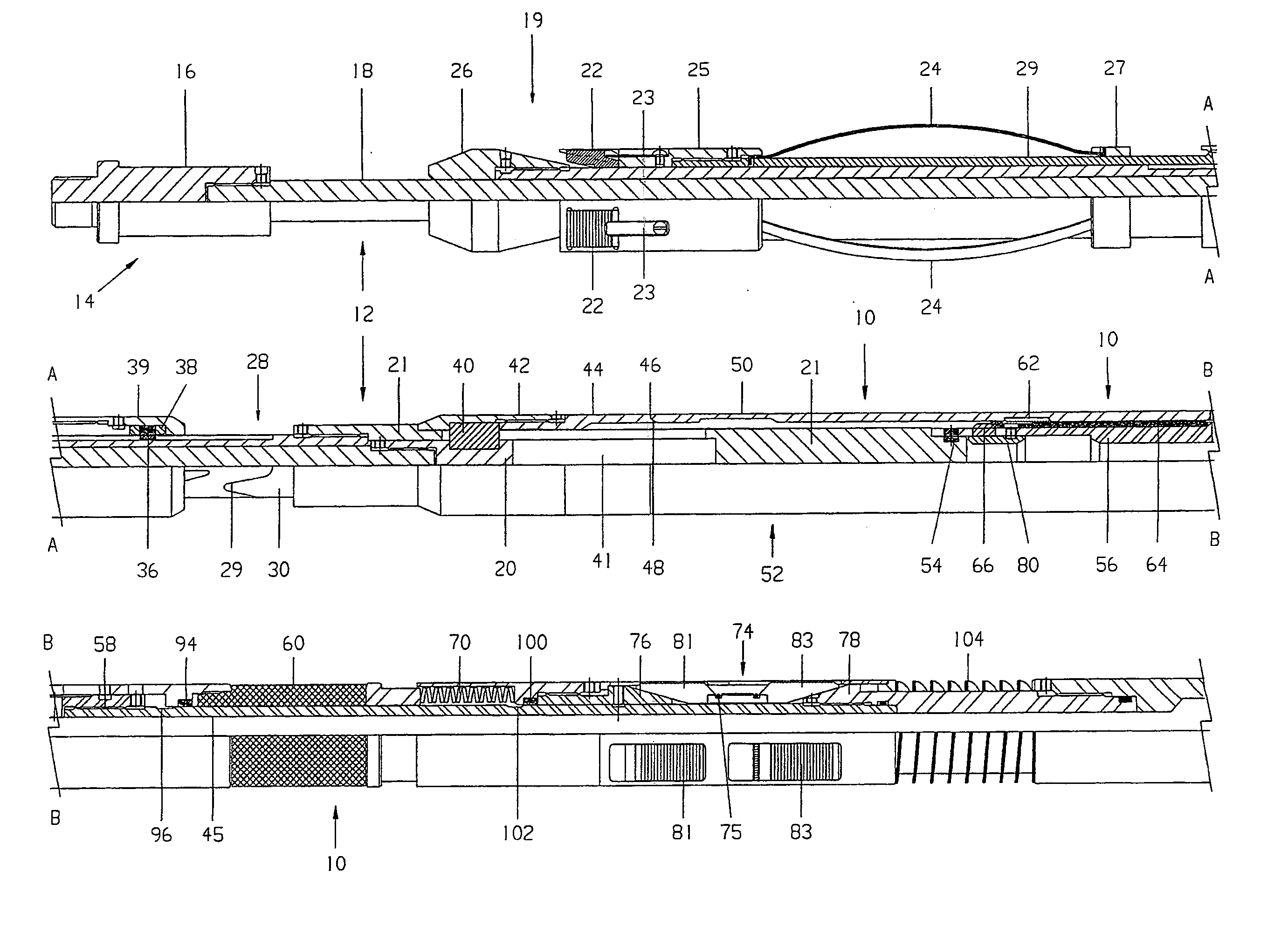
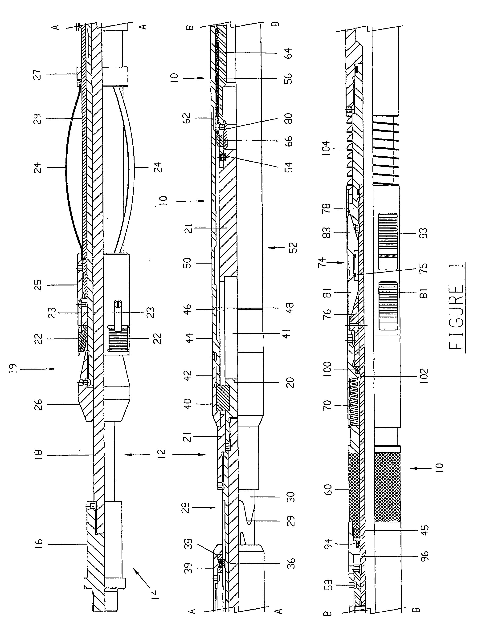
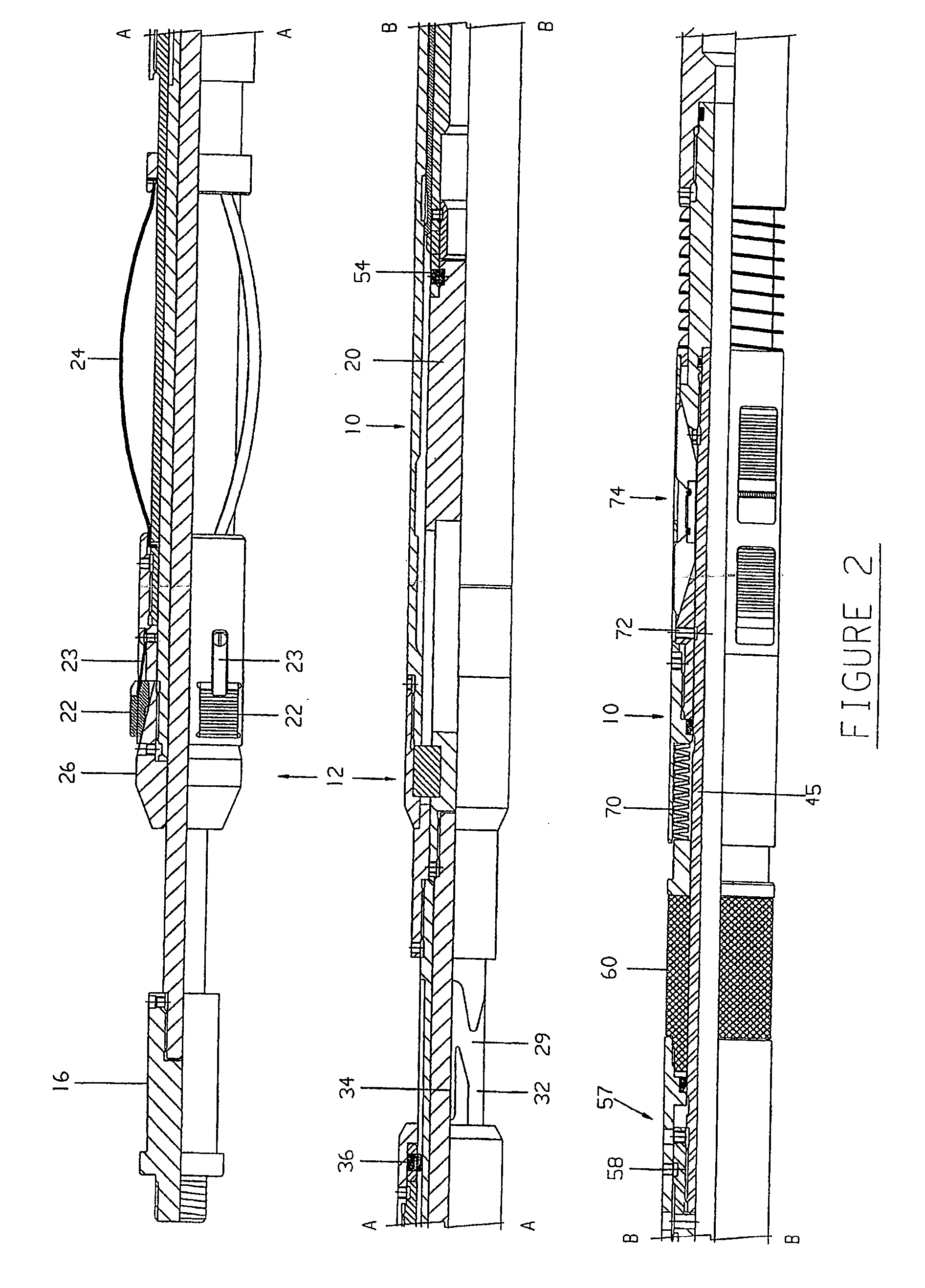
[0025] Advantageously the downhole tool anchoring means are positioned below the downhole tool sealing means so that debris may not fall below the sealing means and foul the downhole tool anchoring means. When the downhole tool is provided with a sealing means, the downhole tool may further comprises a pressure equalisation means for equalising any pressure differential that may exist across the downhole tool prior to retrieval.
[0040] means for releasably coupling the downhole tool with the running tool, said means facilitating transfer of axial loads between the running tool and downhole tool during landing and setting of the downhole tool in the well bore and arranged to release the running tool from the downhole tool upon application of an upward jarring force.

Problems solved by technology

Using traditional tools, it only possible to set the tools at the pre-determined locations where a landing nipple or side pocket mandrel has been pre-installed.
The locations of the side pocket mandrels and landing nipples are fixed at the time when the well is designed and installed and add to the cost of designing the well.
Moreover, in order to provide a plurality of landing nipples, the internal diameter of the casing becomes progressively narrower, making it increasingly difficult to accommodate and manipulate downhole equipment.
Any restriction in the diameter of, in particular, a lower section of a well bore makes operation of the well more difficult and may lead to a significant loss of potential production from the reservoir.
This loss of production is due to a pressure drop created across each well bore restriction.
The Zwart design has several problems.
The complex arrangement of nested sleeves results in a concomitant reduction in the internal diameter of the downhole tool itself.
This makes it difficult to accommodate the passage of other downhole equipment through the hollow bore of the Zwart bridge plug to a lower level.
The reduced bore of the Zwart bridge plug also restricts production flow through the internal diameter of the set bridge plug.
The setting and retrieval operations of the Zwart bridge plug are quite complex, the Zwart bridge plug being provided with a large number of shear pins each of which control relative axial movement of a series of nested sleeves, the setting and retrieval operations requiring a complex series of upward and downward forces to be applied in a particular sequence to shear the pins in a particular order.
Given that bridge plugs can be deployed at large depths down a well bore, it can be extremely difficult for a operator at the surface to determine whether or not the setting or retrieval operation is progressing as required when using the Zwart bridge plug.

Method used


Image

  • Retrievable downhole tool and running tool
  • Retrievable downhole tool and running tool
  • Retrievable downhole tool and running tool

Examples


Embodiment Construction

[0064] Before the preferred embodiments of the present tools are described, it is to be understood that the present invention is not limited to the particular types of anchoring, setting and / or sealing means described. It is also to be understood that the terminology used herein is for the purpose of describing particular embodiments only, and is not intended to limit the scope of the present invention. Unless defined otherwise, all technical and scientific terms used herein have the same meanings as commonly understood by one of ordinary skill in the art to which this invention belongs.

[0065] Throughout this specification reference is made to the tools being set in a “well bore”. The term “well bore” refers to a cased well lined with one or more strings of drillpipe or tubing. Thus, reference to engagement of a component with the well bore refers to engagement of the component with the internal diameter of the tubular used to line and / or case the well bore.

[0066] The term “downho...


PUM


Abstract

A downhole tool and a running tool are described, each being retrievably settable within a suitably sized cased well bore without the need for any interaction between the downhole tool or the running tool and any restrictions or recesses in the well bore to land, anchor or retrieve either tool. The downhole tool has a mandrel, an anchoring means mounted on the mandrel and controllably reconfigurable from a retracted configuration to permit movement of the downhole tool through the well bore to a radially expanded configuration for releasably engaging the cased well bore. The downhole tool anchoring means is reconfigured using a ratchet that resists movement of the tool anchoring means from the expanded configuration back to the retracted configuration until a release mechanism is released to allow retraction of the downhole tool anchoring means and retrieval of the downhole tool from the well bore.

Description

CROSS REFERENCE TO RELATED APPLICATIONS [0001] This application is a continuation of PCT / AU02004 / 001527, filed Nov. 5, 2004, and titled “A Retrievable Downhole Tool and Running Tool,” which claims priority to Australian Application No. AU 2003906144, filed on Nov. 7, 2003, and to Australian Application No. AU 2004905951, filed on Oct. 15, 2004, the entire contents of which are hereby incorporated by reference.FIELD OF THE INVENTION [0002] The present invention relates to a well tool that is settable at any location within the bore of a well and can be subsequently retrieved to the surface. The present invention further relates to a running tool for running and setting a retrievable well tool. [0003] The running tool and / or well tool of the present invention may be used in any type of cased well, including sub-sea wells, platform wells and land wells. The present invention relates particularly, though not exclusively to wells used for oil and / or gas production, but is also applicable...

Claims


Application Information

Patent Timeline
IPC IPC(8): E21B33/129E21B23/00E21B23/06
CPCE21B23/006E21B33/129E21B23/06E21B23/00E21B23/004E21B23/01E21B23/03E21B33/128
Inventor MANSON, DAVID JOHN COPELAND
Owner SCHLUMBERGER TECH CORP
Learn More