Insufflation pump

Active Publication Date: 2016-08-25
MILLER MEDICAL LLC
View PDF5 Cites 3 Cited by
  • Summary
  • Abstract
  • Description
  • Claims
  • Application Information

AI Technical Summary

Benefits of technology

[0011]It is, therefore, an object of the present invention to provide an insufflation pump including a pump body having a first end and a second end. The pump body includes a syringe mechanism at the first end and an actuation mechanism at

Problems solved by technology

Not properly positioning the angioplasty balloon may result in damage to a normal portion of the vessel, while not holding the catheter in place could result in undesired movement of the angioplasty balloon, with subsequent traumatic vessel dissection.
This results in, as a best-case

Method used


Image

  • Insufflation pump
  • Insufflation pump
  • Insufflation pump

Examples


Example

[0031]The detailed embodiments of the present invention are disclosed herein. It should be understood, however, that the disclosed embodiment is merely exemplary of the invention, which may be embodied in various forms. Therefore, the details disclosed herein are not to be interpreted as limiting, but merely as a basis for teaching one skilled in the art how to make and / or use the invention.

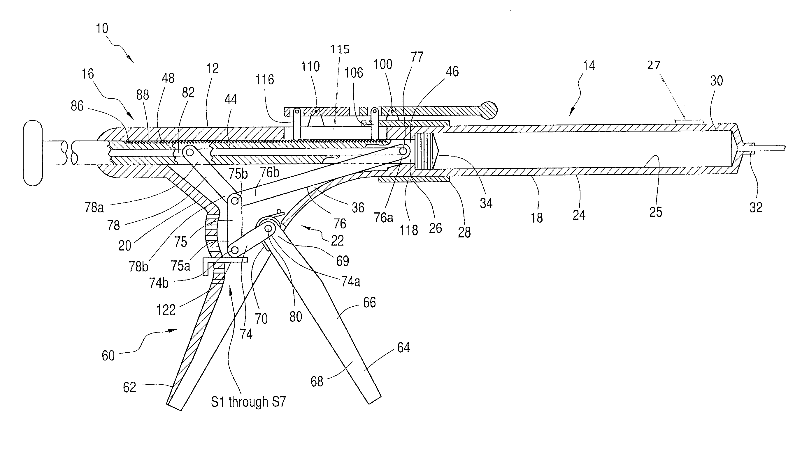
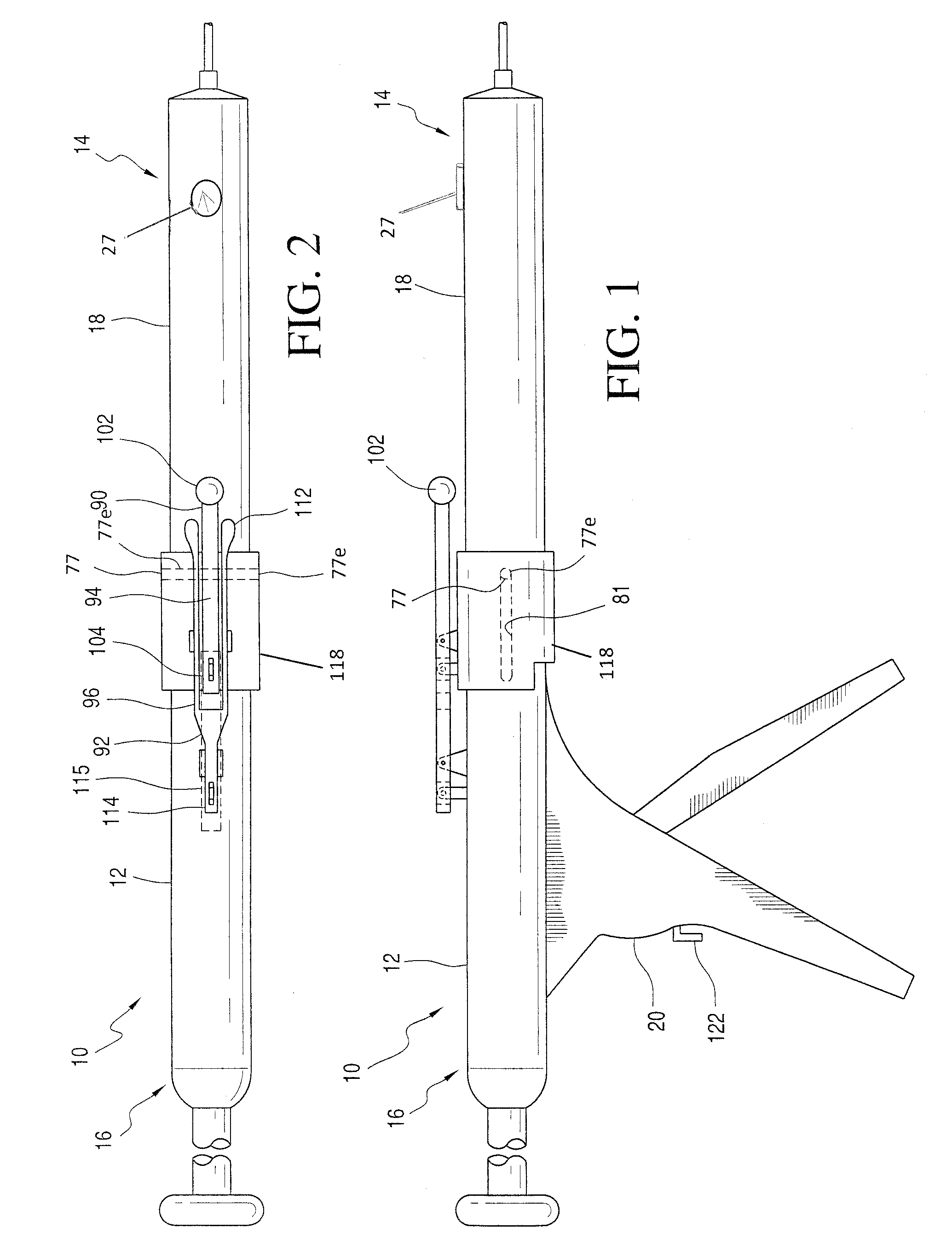
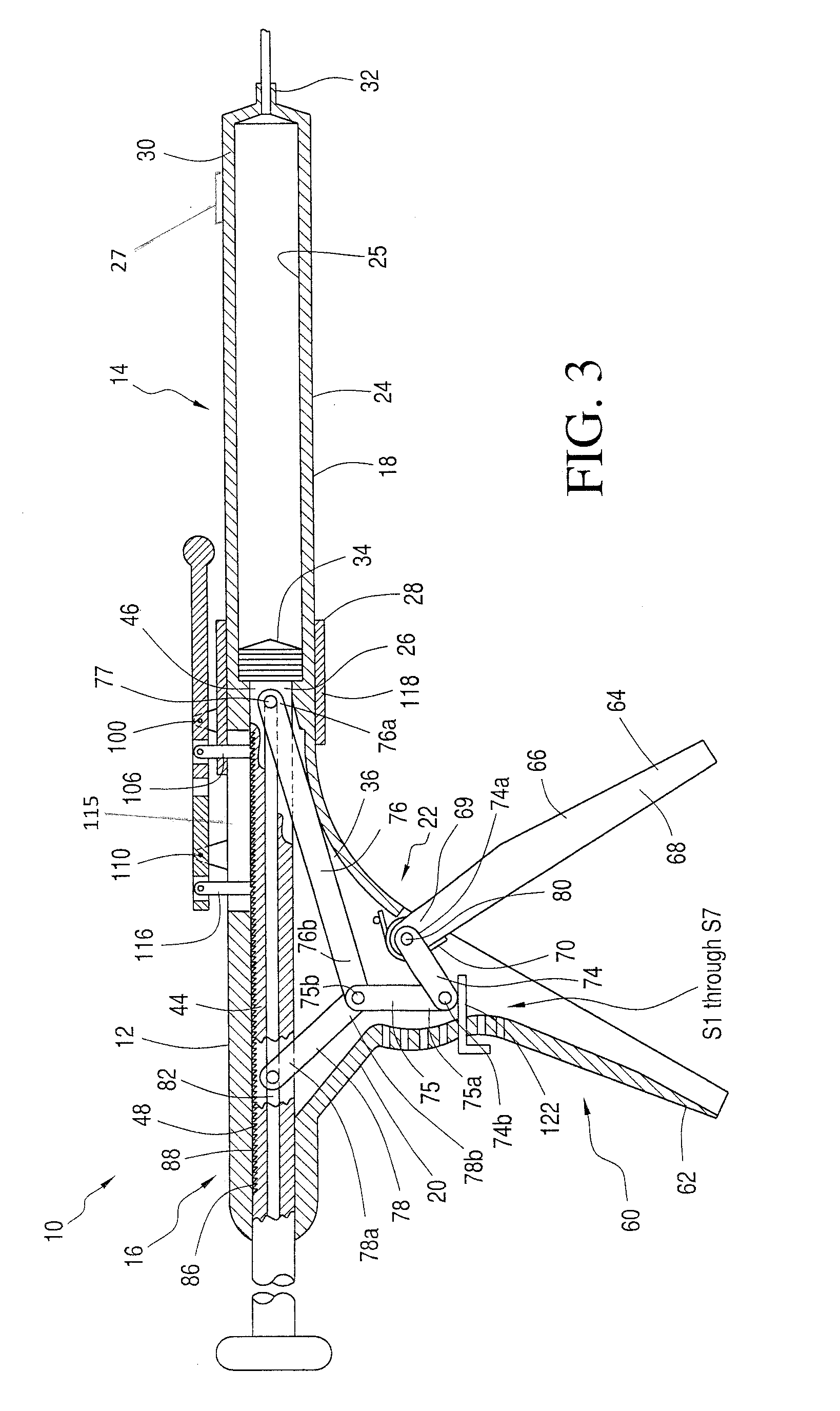
[0032]Referring to FIGS. 1 to 6, an insufflation pump 10 is disclosed. The insufflation pump 10 allows for single handed actuation for inflation of dilatation balloons and other inflatable devices employed during medical procedures.

[0033]The insufflation pump 10 includes a pump body 12 having a first end 14 and a second end 16. The first end 14 is provided with a syringe mechanism 18 and the second end 16 is provided with an actuation mechanism 20. The syringe mechanism 18 and the actuation mechanism 20 are linked by a toggle assembly 22 facilitating the transfer of power from the actuation mecha...


PUM


Abstract

An insufflation pump includes a pump body having a first end and a second end. The pump body includes a syringe mechanism at the first end and an actuation mechanism at the second end. The syringe mechanism includes a plunger. The plunger of the syringe mechanism and the actuation mechanism are linked by a toggle assembly facilitating transfer of power from the actuation mechanism to the syringe mechanism.

Description

CROSS REFERENCE TO RELATED APPLICATION[0001]This application claims the benefit of U.S. Provisional Application Ser. No. 62 / 118,127, entitled “INSUFFLATION PUMP,” filed Feb. 19, 2015.BACKGROUND OF THE INVENTION[0002]1. Field of the Invention[0003]The invention relates to an insufflation pump.[0004]2. Description of the Related Art[0005]Most vascular procedures are now performed in an endovascular fashion; that is, by way of a catheter placed inside of an artery or vein. The benefit of an endovascular, versus a traditional “open”, surgical procedure is the greatly decreased morbidity and mortality afforded by the endovascular route, while affording similar overall outcomes. Instead of the traditional surgical bypass procedure performed on the heart, legs, as well as other body parts, endovascular percutaneous transluminal angioplasty, or PTA, is now the standard of care for treating narrowed or blocked arteries and veins. Angioplasty is performed to dilate arteries, veins and other c...

Claims


Application Information

Patent Timeline
IPC IPC(8): A61M25/10
CPCA61M25/104A61M25/10182A61M25/10187
Inventor MILLER, STUART H.
Owner MILLER MEDICAL LLC
Why Eureka
Try Eureka