

Interface designed with differential pumping and built-in figure of merit method to monitor chambers where environmentally sensitive samples are prepared and transferred for analysis
- Summary
- Abstract
- Description
- Claims
- Application Information
AI Technical Summary
Benefits of technology
Problems solved by technology
Method used
Image

Examples
Embodiment Construction
Definitions
[0079]Unless defined otherwise, all technical and scientific terms used herein have the same meaning as commonly understood by one of ordinary skill in the art.
[0080]The term “connected” as used herein generally refers to pieces which may be joined or linked together.
[0081]The term “coupled” as used herein generally refers to pieces which may be used operatively with each other, or joined or linked together, with or without one or more intervening members.
[0082]The term “directly” as used herein generally refers to one structure in physical contact with another structure, or, when used in reference to a procedure, means that one process effects another process or structure without the involvement of an intermediate step or component.
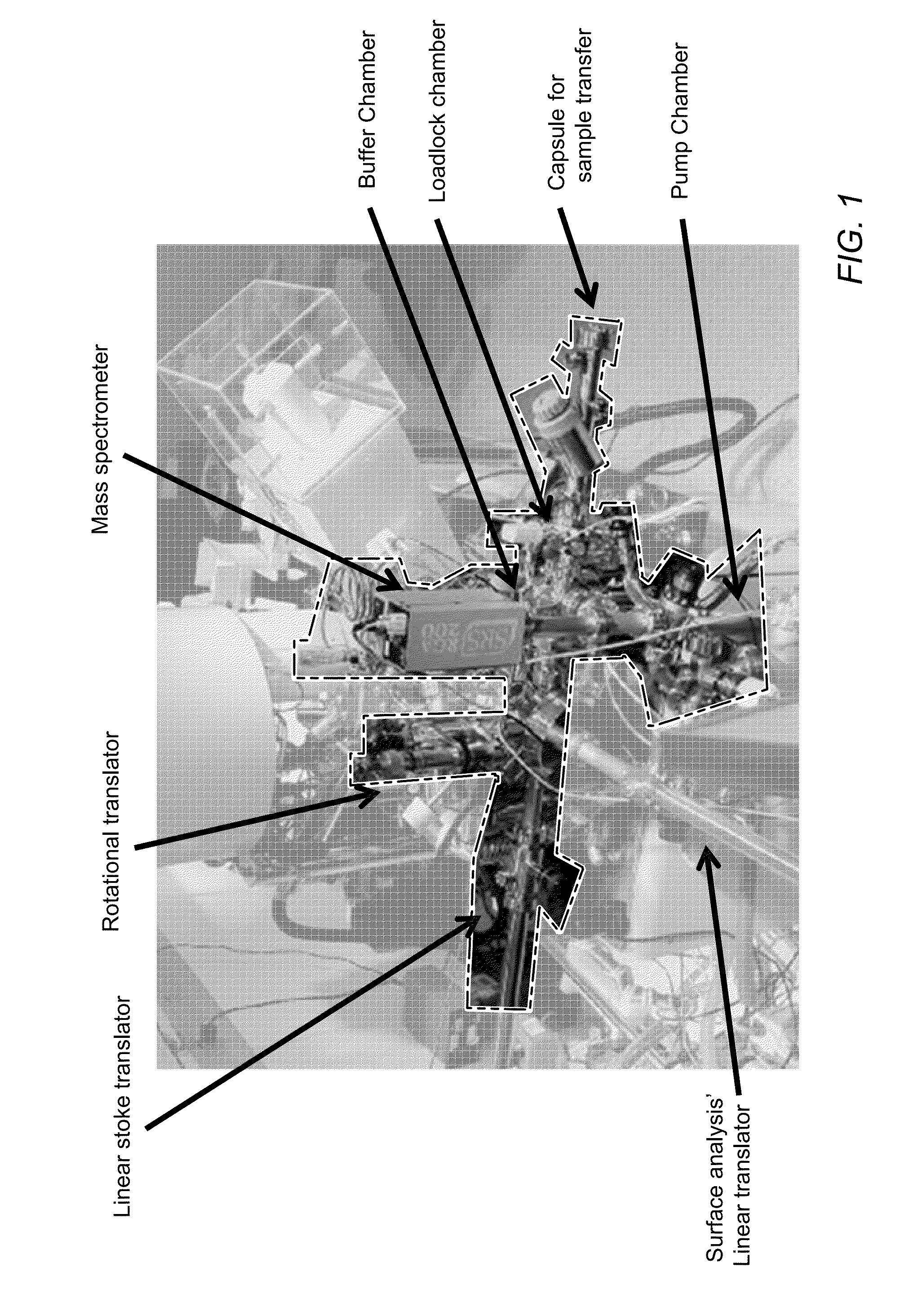
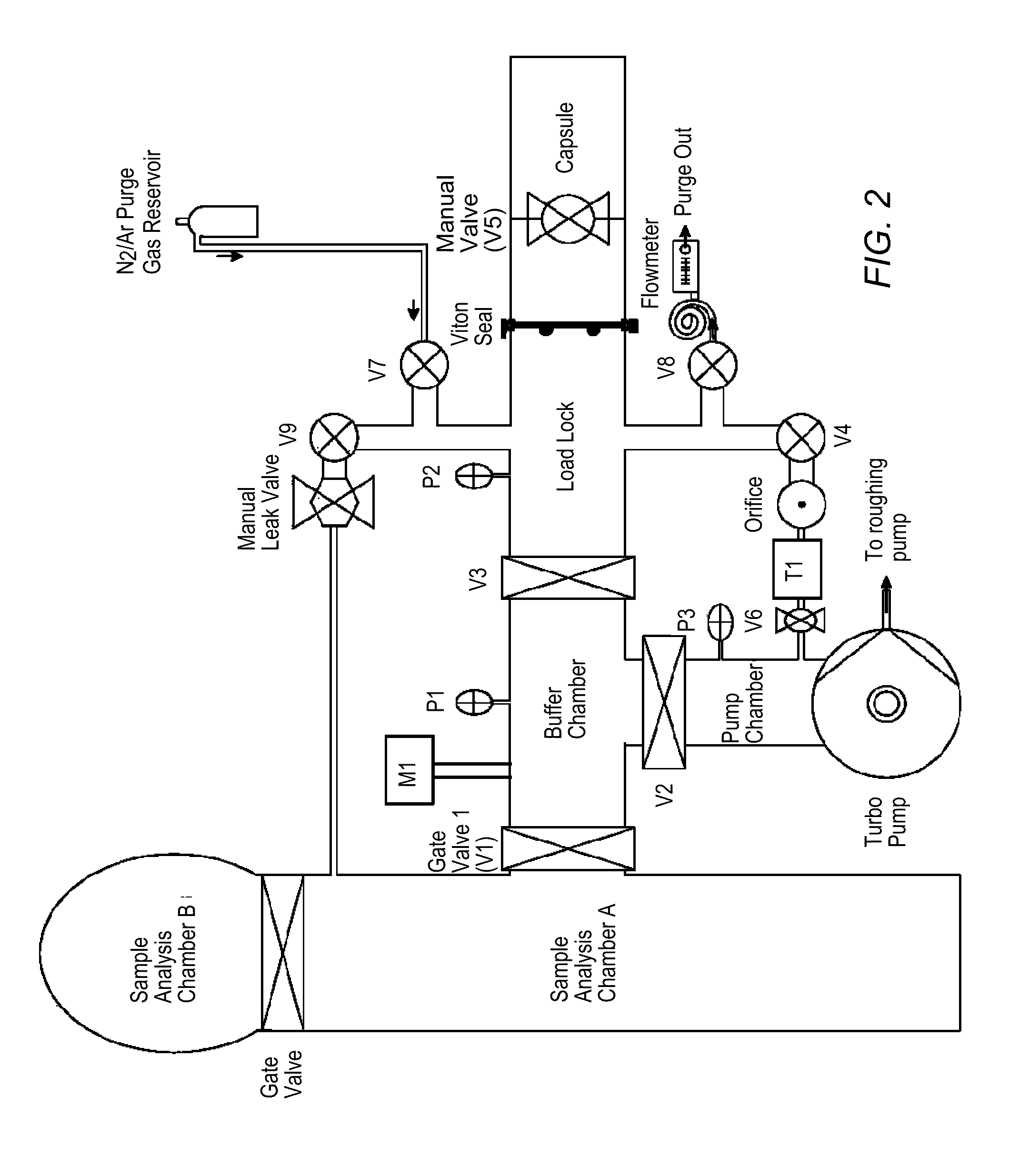
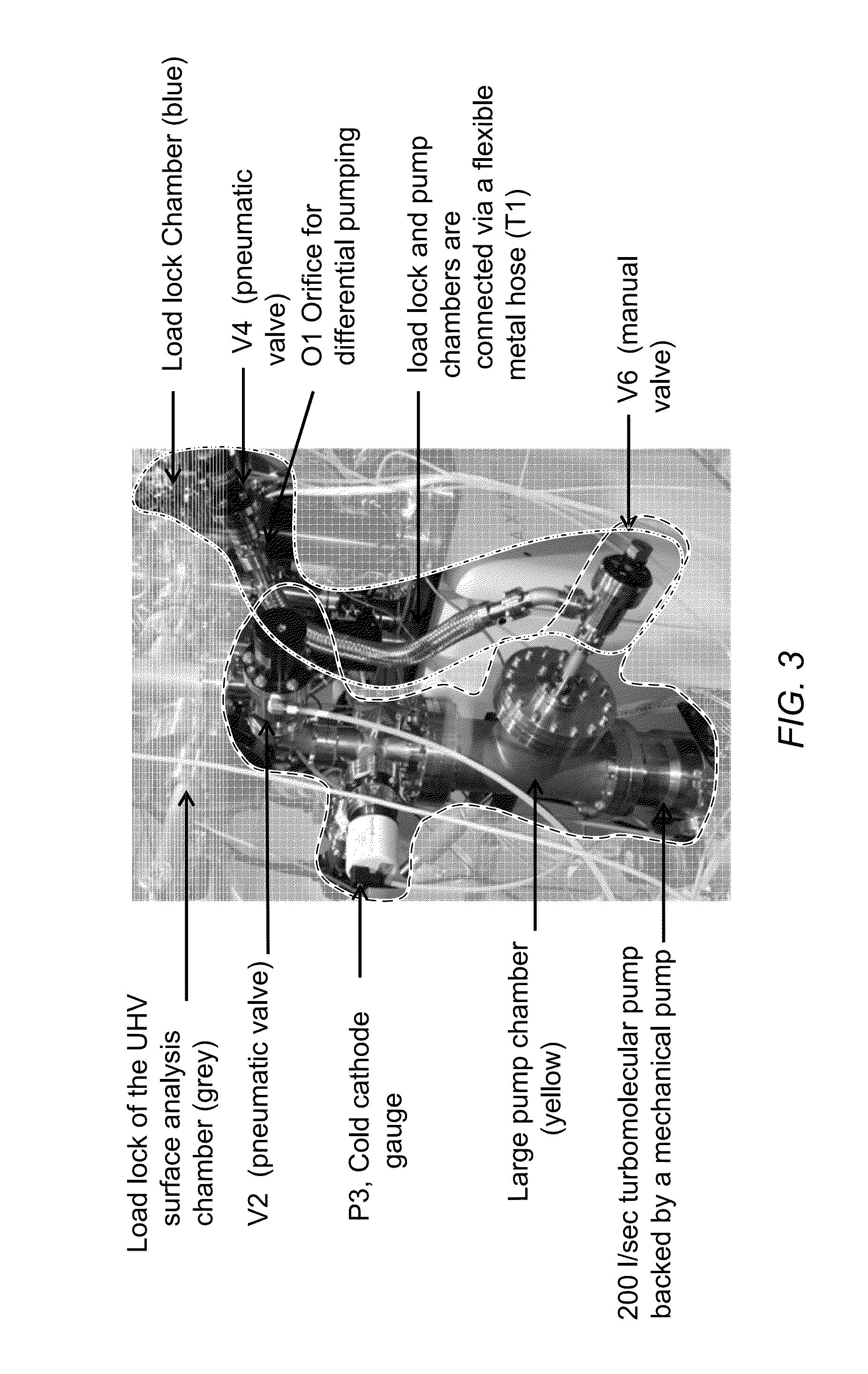
[0083]In some embodiments, a system for transferring sample from ambient pressure to high vacuum may include a carrying capsule, a load lock, a buffer chamber, a pump chamber, and an inert gas reservoir. The Capsule may be coupled to the load ...
PUM
 Abstract
Description
Claims
Application Information