
Fresh air hood system for mini splits

Inactive Publication Date: 2019-04-04
ADAMS DALE W
View PDF0 Cites 3 Cited by
  • Summary
  • Abstract
  • Description
  • Claims
  • Application Information

AI Technical Summary

Benefits of technology

The patent text describes a new system for adding fresh air to mini splits, which can be used with any type of mini split system. The system includes a damper that controls the amount of fresh air that can be added to a room or building. The damper can be manually operated or controlled using a wireless remote control. The technical effect of this patent is to provide a more efficient and versatile method for adding fresh air to mini splits.

Problems solved by technology

While conventional heating and air conditioning systems are effective, they suffer from many disadvantages.
Namely, many heating and air condition systems require complex, expensive and difficult to install ductwork to facilitate bringing fresh air into a room.
However, due to the complexity and expense associated with the installation of ductwork in association with a mini split system, many mini split systems are simply installed without the ability to bring fresh outside air into a room or building.
As such, while these mini split systems are effective at heating or cooling a room or building, they are not effective at meeting new and more-stringent fresh air requirements within the room or building.
However, mini split systems suffer from a number of disadvantages such as the inability to bring fresh outdoor air into a room or building.
However, users of a mini split system have very limited options to bring outdoor air into a room or building, and the existing options are all undesirable (such as running conventional ductwork).
Another complexity and complication in this area of art is that building codes and best practices have placed increased demands on ventilation systems and minimum fresh air flow into a room or building.
While mini split systems may be utilized to heat and cool a room or building, conventionally it is difficult, and in many applications and installations impossible, to utilize a mini split system to meet or contribute to meeting ASHRAE Standard 62.2.

Method used


Image

  • Fresh air hood system for mini splits
  • Fresh air hood system for mini splits
  • Fresh air hood system for mini splits

Examples


Embodiment Construction

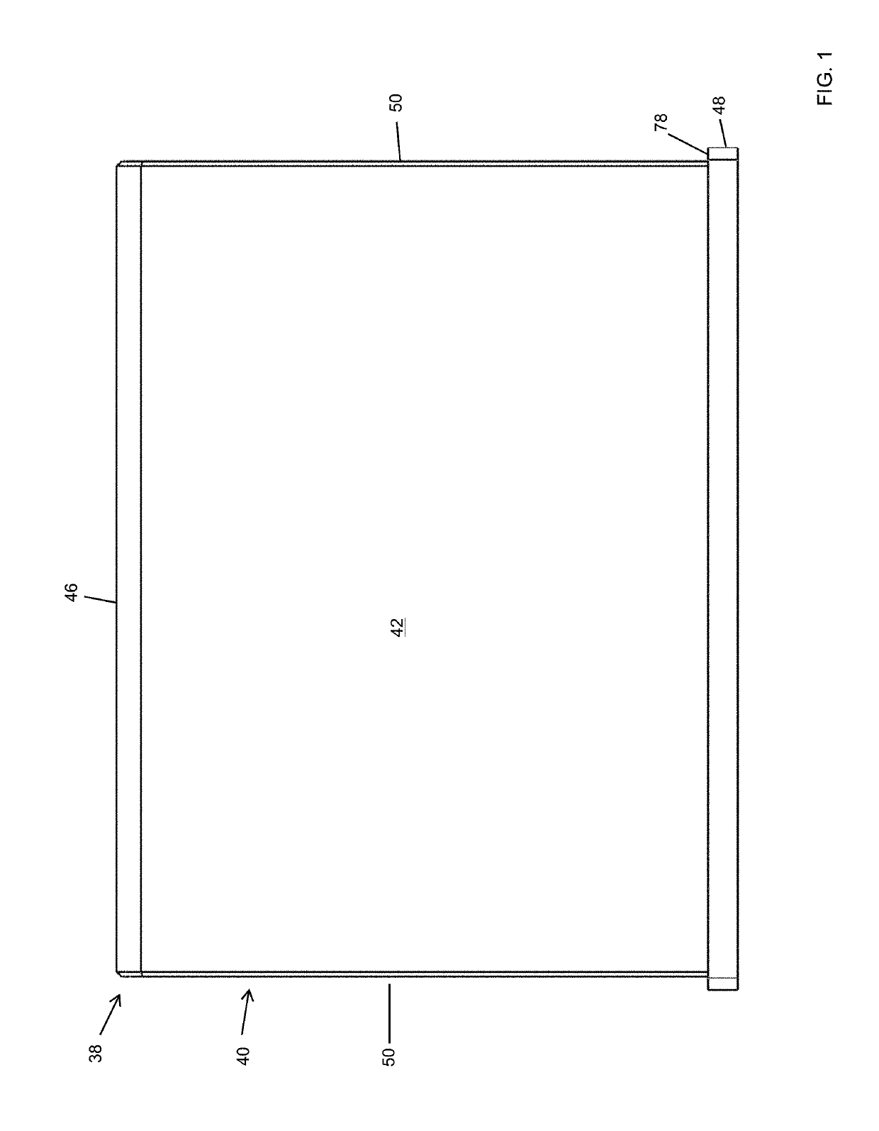
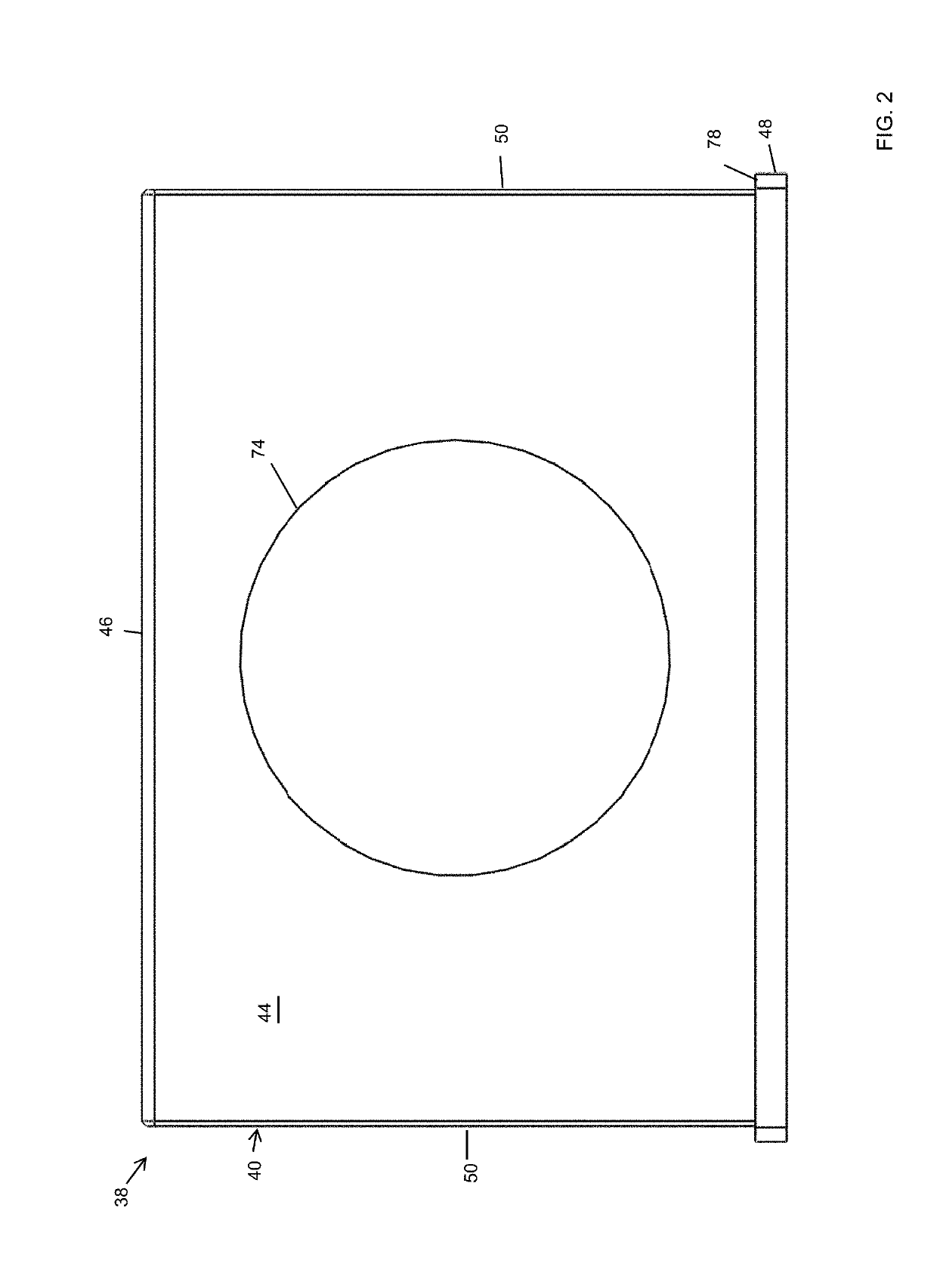
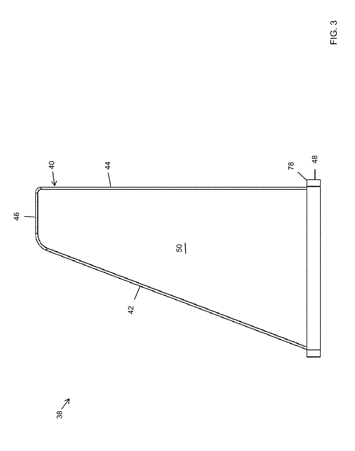
[0076]In the following detailed description of the embodiments, reference is made to the accompanying drawings which form a part hereof, and in which is shown by way of illustration specific embodiments in which the disclosure may be practiced. These embodiments are described in sufficient detail to enable those skilled in the art to practice the disclosure, and it is to be understood that other embodiments may be utilized and that mechanical, procedural, and other changes may be made without departing from the spirit and scope of the disclosure. The following detailed description is, therefore, not to be taken in a limiting sense, and the scope of the disclosure is defined only by the appended claims, along with the full scope of equivalents to which such claims are entitled.

[0077]As used herein, the terminology such as vertical, horizontal, top, bottom, front, back, end and sides are referenced according to the views presented. It should be understood, however, that the terms are ...


PUM


Abstract

A fresh air hood system for mini splits that can be used with any type of mini split system. The system comprises a damper, among many other components, wherein the damper contains a control mechanism which facilitates the transfer of a controlled amount of fresh air into a room or building. In one embodiment, the system comprises a control mechanism that is manually operated, such as a pull string. In one embodiment, the system comprises a control mechanism that is a wireless control, such as a conventional remote control that transmits radio frequency signals over the air.

Description

CROSS REFERENCE TO RELATED APPLICATIONS[0001]This applications claims priority to U.S. Provisional Application No. 62 / 568,064 which was filed on Oct. 4, 2017, the entirety of which is incorporated herein fully by reference.FIELD OF THE DISCLOSURE[0002]This disclosure relates generally to heating and air conditioning units. More particularly, and without limitation, to a fresh air hood system for mini split systems.BACKGROUND OF THE DISCLOSURE[0003]Heating and air conditioning systems are old and well known in the art. Conventional heating and air conditioning systems operate to raise or lower the temperature within a room or building by circulating heated or cooled air. While conventional heating and air conditioning systems are effective, they suffer from many disadvantages. Namely, many heating and air condition systems require complex, expensive and difficult to install ductwork to facilitate bringing fresh air into a room.[0004]In recent years, what are known as mini split syste...

Claims


Application Information

Patent Timeline
IPC IPC(8): F24F1/32F24F1/62F24F13/10F24F7/003
CPCF24F1/32F24F1/62F24F13/10F24F2007/003F24F11/0001F24F13/082F24F2221/52F24F1/0035F24F2007/0025F24F7/003
Inventor ADAMS, DALE W.
Owner ADAMS DALE W
Learn More