
LIF socket connector

a socket and socket technology, applied in the direction of coupling device connection, electrical apparatus construction details, engagement/disengagement of coupling parts, etc., can solve the problems of inconvenient pin insertion or removing of the corresponding spring arm, and insufficient flexibility of the whole contact. , to achieve the effect of convenient pin insertion

Active Publication Date: 2006-12-07
HON HAI PRECISION IND CO LTD
View PDF4 Cites 0 Cited by
  • Summary
  • Abstract
  • Description
  • Claims
  • Application Information

AI Technical Summary

Benefits of technology

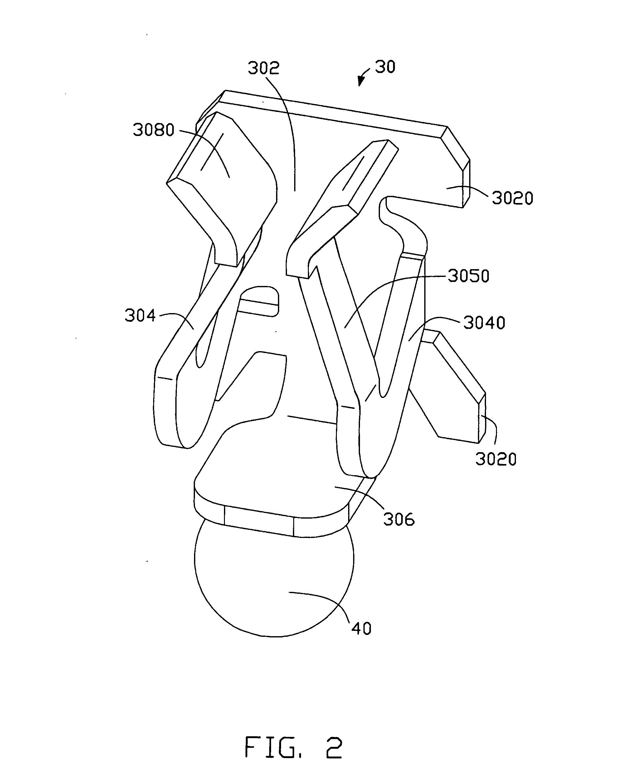
The present invention provides a LIF socket that is convenient for pins of an IC package to be inserted into or taken out of. The LIF socket includes a housing with a supporting surface and a mounting surface opposite to the supporting surface. A number of passages extends from the mounting surface. Each passage has a leading section. A plurality of contacts is disposed in the corresponding passages, respectively. Each contact has a planar body, a pair of arms extending from two lateral sides of the planar body towards the supporting surface, and a soldering pad angled with respect to the planar body. The arm is formed with a curved contacting section at a distal end thereof. The curved contacting section is provided with a smooth curved surface. The elasticity of the spring arms is improved by disposing curved contacting sections on the arms of the contacts to increase an extending length of the arms. The pins of the IC package can easily insert into or withdrawn from the spring arms by disposing smooth curved surface on the contact. The pins of the IC package can rapidly insert into the corresponding arms during assembling by presence of the leading slot and the smooth curved surface on the contact portion of the contact.

Problems solved by technology

However, one problem can be encountered when assembling the IC package onto the LIF socket.
The problem is that only the spring arms of the contact are elastically deformed and the flexibility of the whole contact is not good enough.
Another problem is that each pin of the IC package can not be easily inserted into or withdrawn from the corresponding pair of spring arms because the contact portions of the contact are curve-configured, which raises high resistance.
In addition, if the pins of the IC package offset from a normal position during assembling, the spring arms of the contact will be broken easily because of the interferential force between the pins and the spring arms.

Method used


Image

  • LIF socket connector
  • LIF socket connector
  • LIF socket connector

Examples


Embodiment Construction

[0022] Reference will now be made to the drawings to describe the present invention in detail.

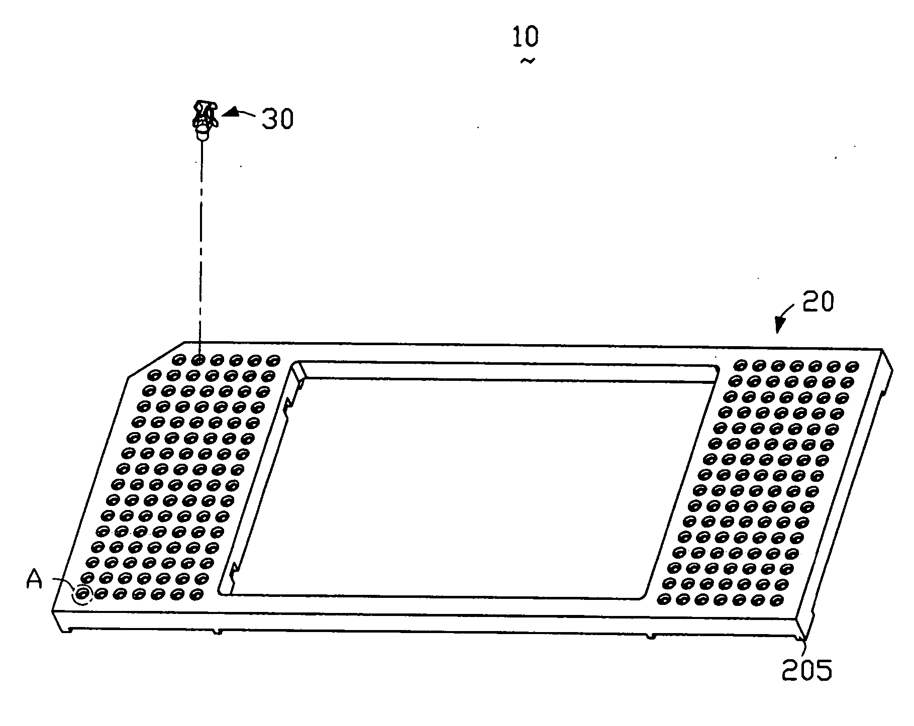
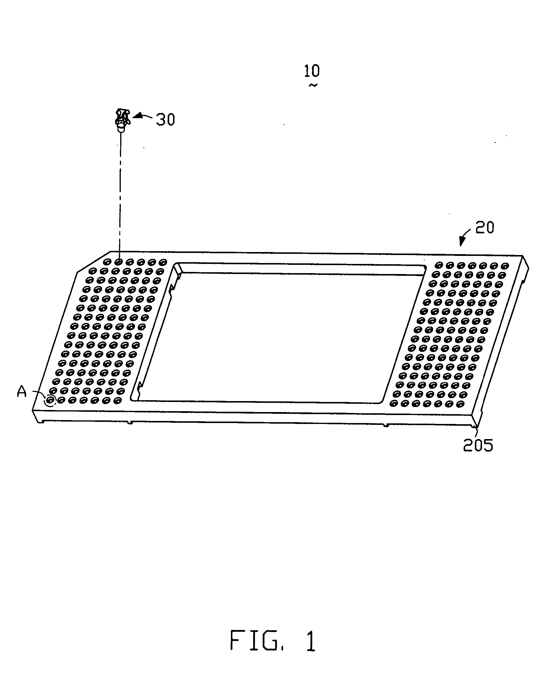
[0023]FIG. 1 is an assembled view of a LIF socket 10 for electrically connecting an IC package (not shown) and a PCB (not shown) in accordance with a preferred embodiment of the present invention. The socket 10 comprises a housing 20 and a plurality of contacts 30 received therein.

[0024] As indicated in FIGS. 1, 5 and 7, the housing 20 is made of insulating material and is rectangular. The housing 20 has a supporting surface 202 and a mounting surface 204 opposite to the supporting surface 202. A number of standoffs 205 is provided at four corners of the mounting surface 204 as no known for the purpose of subsequent soldering process.

[0025] A number of passages 206 extends from the mounting surface 204. Each passage 206 comprises a leading section 210, a connecting section 212, and a base section 208. The connecting section 212 is a circular aperture and a diameter thereof is greater tha...


PUM


Abstract

A LIF socket (10) for electrically connecting an IC package and a PCB includes an insulative housing (20) having a supporting surface (202) and a mounting surface (204) opposite to the supporting surface. A number of passages (206) extend from the mounting surface. Each passage has a leading section (208). A number of contacts (30) are disposed in corresponding passages, respectively. Each contact has a planar body (302), a pair of arms (304) extending from two lateral sides of the planar body towards the supporting surface, and a soldering pad (306) angled with respect to the planar body. The arm is formed with a curved contacting (3080) section at a distal end thereof.

Description

BACKGROUND OF THE INVENTION [0001] 1. Field of the Invention [0002] The present invention relates to a LIF (low insertion force) socket for electrically connecting an IC (integrated circuit) package and a PCB (printed circuit board). [0003] 2. Description of the Prior Art [0004] LIF sockets are widely used in computers, and are generally used for electrically connecting two separate electrical components. Accordingly, data and signal's transmission between the two components is achieved. [0005] A typical LIF socket generally includes an insulative housing and a plurality of contacts disposed in corresponding passages of the housing, respectively. Each contact defines a pair of touching pads for contacting with a corresponding pin of an IC package, and a soldering pad opposite to the touching pad. When the IC package is mounted on the LIF socket and is pressed, each pin contacts the corresponding pair of touching pads of the contact. Accordingly, the IC package is electrically connec...

Claims


Application Information

Patent Timeline
Patent Type & Authority Applications(United States)
IPC IPC(8): H01R4/50
CPCH05K7/1084H01R13/112H01R13/62H01R13/629H01R33/76
Inventor LIAO, FANG-JWULIN, NICK
Owner HON HAI PRECISION IND CO LTD
Learn More