Food processor and knife group mounting structure and stirring cup thereof

A food cooking machine and installation structure technology, which is applied in the field of household electrical appliances, can solve the problems of time-consuming and laborious, inconvenient disassembly and assembly, and achieve the effects of avoiding time-consuming and laborious, reducing operating strength, and improving the convenience of use

Pending Publication Date: 2021-01-19
GUANGDONG MIDEA CONSUMER ELECTRICS MFG CO LTD
View PDF0 Cites 1 Cited by
  • Summary
  • Abstract
  • Description
  • Claims
  • Application Information

AI Technical Summary

Problems solved by technology

Therefore, when disassembling and assembling the knife set, either choose manual operation, which is time-consuming and laborious, or require additional tools, which is inconvenient for disassembling and assembling

Method used


Image

  • Food processor and knife group mounting structure and stirring cup thereof
  • Food processor and knife group mounting structure and stirring cup thereof
  • Food processor and knife group mounting structure and stirring cup thereof

Examples


Embodiment 1

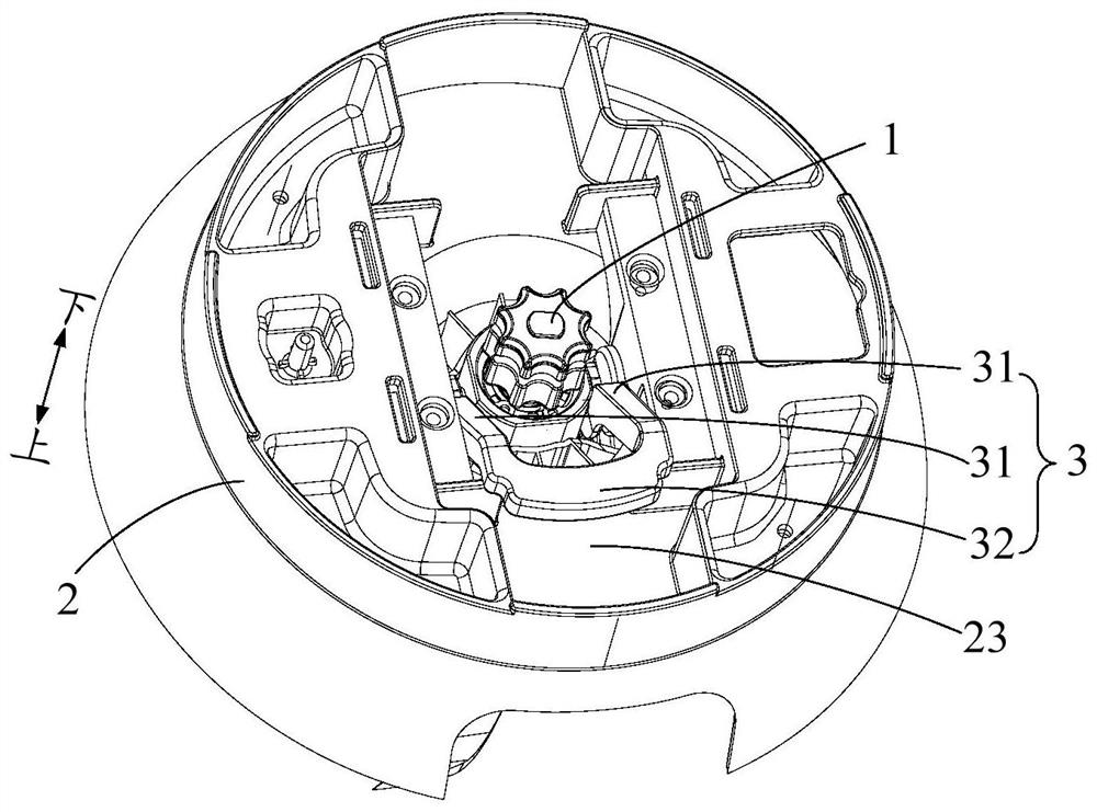
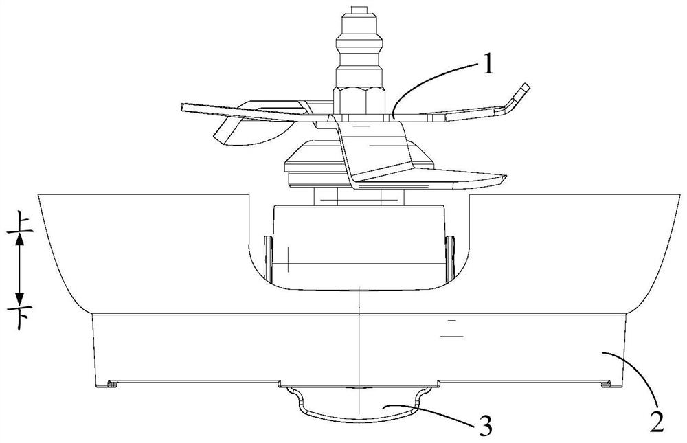
[0099] Such as figure 2 , image 3 with Figure 4 As shown, the knife set installation structure of the food cooking machine provided by the embodiment of the first aspect of the present invention includes: a container bottom 2, a knife seat 11 and a locking component.

[0100] Specifically, the bottom wall of the container bottom 2 is provided with a mounting hole 24, such as Figure 13 As shown; the knife seat 11 is installed at the installation hole 24 for installing the knife 12 of the food cooking machine; the locking part is installed on the bottom 2 of the container, matched with the knife seat 11, and is suitable for removing the knife relative to the bottom 2 of the container Reciprocate between the knife lock position, and lock the knife seat 11 to fix the knife seat 11 when moving to the knife lock position (such as Figure 5 with Image 6 shown), and unlock the knife seat 11 to release the knife seat 11 when moving to the knife removal position (such as Figu...

Embodiment 2

[0145] The difference with Embodiment 1 is: on the basis of Embodiment 1, further, the wrench 3 is provided with a limiter, and the bottom 2 of the container is provided with a limiter fit. Next, the limit part and the limit fit part are in contact with each other, such as Figure 9 with Figure 10 As shown, to limit the rotation range of the wrench 3.

[0146] The rotation range of the wrench 3 is limited by the stop fit of the limit part and the limit fit part, and a sense of in-position will be generated during the process of disassembling and assembling the knife set 1, so that it can play the role of assembly positioning, and at the same time, it can prevent the wrench 3 from After the rotation is in place, it continues to rotate, which improves the reliability of use.

[0147] Optionally, one of the limiting portion and the limiting fitting portion is a limiting protrusion 21, and the other is a limiting groove 315, such as Figure 9 with Figure 10 shown.

[0148] ...

Embodiment 3

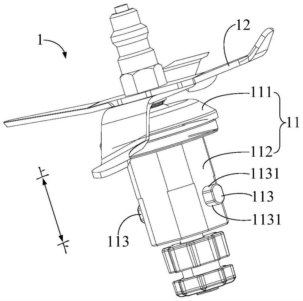
[0160] The difference with Embodiment 2 is that: on the basis of Embodiment 2, further, the number of locking protrusions 113 is two, and the two locking protrusions 113 are arranged symmetrically at 180° with respect to the central axis of the tool holder 11, as figure 1 As shown, the number of locking grooves 311 is equal to the number of locking protrusions 113 and corresponds one by one; the wrench 3 is U-shaped, as figure 2 , Figure 5 with Figure 7 As shown, it includes two rotating arms 31 parallel to each other and a connecting arm 32 connecting the two rotating arms 31. The ends of the two rotating arms 31 away from the connecting arms 32 are rotationally connected to the bottom 2 of the container, and the two rotating arms 31 are respectively A locking protrusion 113 or a locking groove 311 is provided.

[0161] The number of locking protrusions 113 is two, and the two locking protrusions 113 are arranged symmetrically at 180° with respect to the central axis of ...


PUM


Abstract

The invention provides a food processor and a knife group mounting structure and a stirring cup thereof, the knife group mounting structure comprises: a container bottom, wherein the bottom wall of the container bottom is provided with a mounting hole; a tool apron which is mounted at the mounting hole and is used for mounting a tool of the food processor; and a locking part which is arranged at the bottom of the container, is matched with the tool apron, is suitable for doing reciprocating motion between a tool dismounting position and a tool locking position relative to the bottom of the container, locks the tool apron to fix the tool apron when moving to the tool locking position, and unlocks the tool apron to loosen the tool apron when moving to the tool dismounting position. Accordingto the invention, the knife group can be disassembled and assembled by operating the locking part, and rapid disassembly and assembly of the knife group are facilitated. Meanwhile, the locking part is directly mounted at the bottom of the container and cannot be separated from the bottom of the container in the using process, so that the locking part can be prevented from being lost or confused with other tools; and loosening of the tool apron due to loosening of the nut when the tool rotates in one direction can be prevented, so that the use reliability of the product is improved.

Description

technical field [0001] The present invention relates to the technical field of household electrical appliances, in particular to a knife set installation structure of a food cooking machine, a stirring cup including the knife set installation structure, and a food cooking machine including the stirring cup. Background technique [0002] At present, in food processors such as wall breakers on the market, the knife set is fixed in such a way that the knife set passes through the bottom of the cup, and then a nut or a screw structure similar to a nut is used to lock the knife set that passes through the bottom of the cup. When removing the knife unit, it is necessary to loosen the bottom lock nut. Therefore, when disassembling and assembling the knife set, either choose manual operation, which is time-consuming and laborious, or require additional tools, which is inconvenient for disassembling and assembling. Contents of the invention [0003] In order to solve at least one ...

Claims


Application Information

Patent Timeline
Patent Type & Authority Applications(China)
IPC IPC(8): A47J43/046A47J43/07A47J19/00
CPCA47J19/00A47J43/046A47J43/0716A47J43/07
Inventor 刘剑波招绍坤
Owner GUANGDONG MIDEA CONSUMER ELECTRICS MFG CO LTD
Why Eureka
Try Eureka