
Repeatably releasable cable connector

a repeatable, cable connector technology, applied in the direction of connection, electrical apparatus, coupling device connection, etc., can solve the problem of irreparable breakage of the locking mechanism, and achieve the effect of resiliency of the retainer

Inactive Publication Date: 2006-12-07
SCULLY SIGNAL CO
View PDF9 Cites 29 Cited by
  • Summary
  • Abstract
  • Description
  • Claims
  • Application Information

AI Technical Summary

Benefits of technology

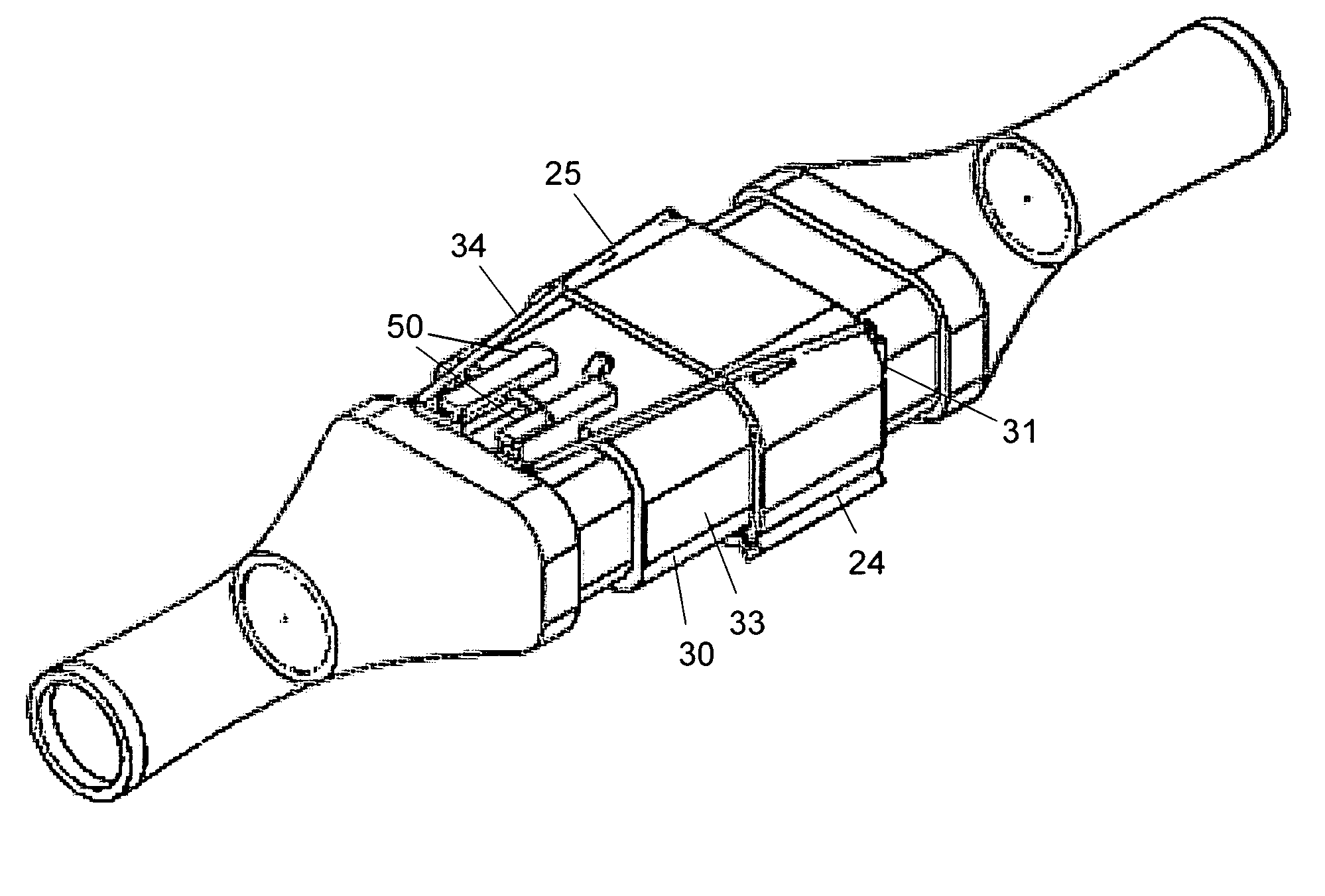
[0006] At least one protrusion may extend from an outer surface of the male connector portion housing. This protrusion has a surface that is transverse to the mating direction, and two protrusions may be provided near each other so as to form a space between them. The female connector housing has a shoulder with at least one latching surface that is also transverse to the mating direction. The transverse surfaces of the male and female connectors are engaged by a resilient retainer that is shaped to fit within a retention position between them. When the retainer resides in the retention position, a portion of it is located to a side of the male connector protrusion away from the female connector portion. Likewise, another portion of the retainer is located to a side of the latching surface of the female connector away from the male connector portion. The female portion may include two such latching surfaces that allow a single spring to be used for the retainer such that, in the retention position, each end of the spring is located adjacent to one of the latching surfaces, while a middle portion of the spring is located adjacent to one or more of the protrusions of the male connector portion. With the retainer in the retention position, it provides a retention force that resists a separation of the male and female connector portions. However, the resiliency of the retainer is such that the retention force may be overcome, and the retainer moved out of the retention position, by a sufficiently large separation force applied to pull the connector portions apart. Thus, separation of the connector portions by force alone, whether intentional or accidental, may occur without damage to the retainer or connector portions.

Problems solved by technology

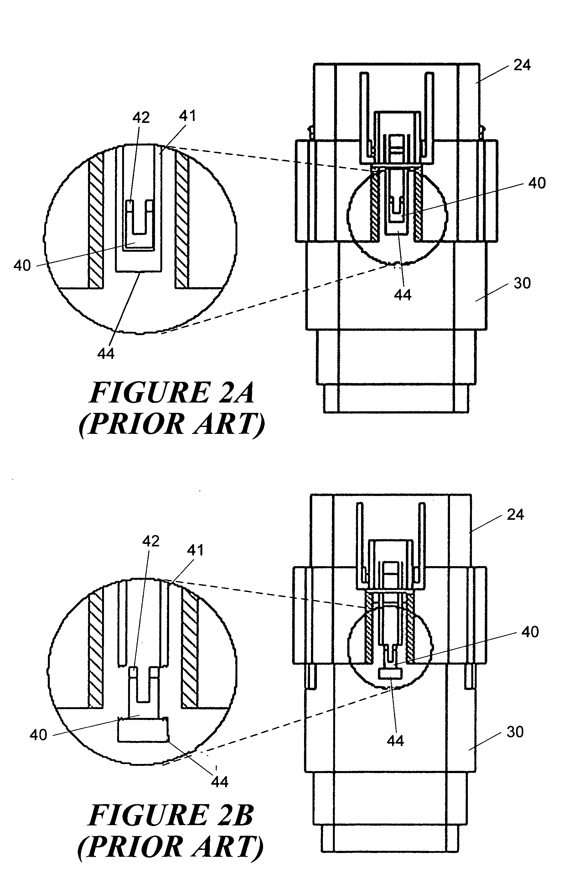
However, upon sufficient force, the locking mechanism will be irreparably broken, requiring either repair or replacement of the connector before it may be used again.

Method used


Image

  • Repeatably releasable cable connector
  • Repeatably releasable cable connector
  • Repeatably releasable cable connector

Examples


Embodiment Construction

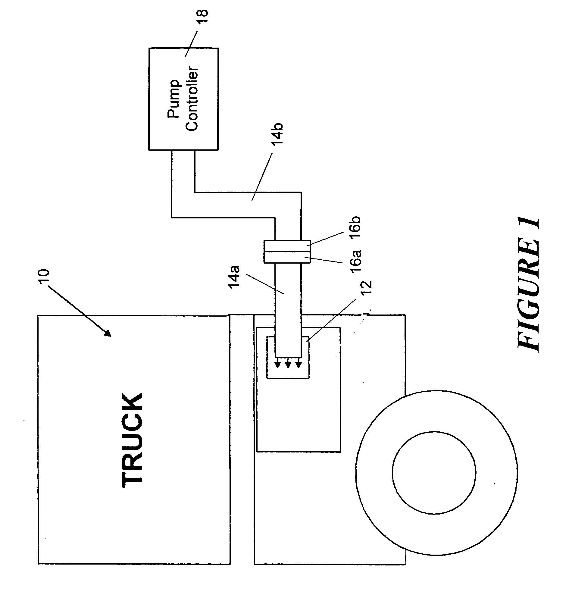
[0014] Shown in FIG. 1 is a schematic view of a portion of a truck 10 used for the transportation of petroleum products such as gasoline. The truck has an electronic panel 12 to which is connected to a truck cable portion 14a, which has at the opposite end a truck cable connector 16a. This cable connector portion 16a mates with a pump controller cable connector portion 16b, which is connected to pump controller cable 14b. The pump controller cable connector portion 16b provides electrical signal paths for a pump controller 18 that are used for controlling the pump of a petroleum loading rack to which the truck is connected. The loading rack provides a source of petroleum product that is loaded into a storage tank of the truck 10 via a fluid conduit (not shown). The transfer of the fluid product is preferably conducted under a number of conditions, including various safety and product identification and tracking protocols. Electrical signals used in these protocols are transmitted al...


PUM


Abstract

A cable connector has male and female connector portions that slide together in a mating direction. The housing of one connector portion has a shoulder with a surface roughly perpendicular to the mating direction. The other connector portion has a resilient retainer spring attached thereto which extends parallel to the mating direction. When the connector portions are mated, the retainer spring has a finger which slips over the shoulder surface and is held in position by the resilience of the spring to provide a retention force that resists a separation of the male and female connector portions. However, the finger is shaped and resilience of the retainer spring is such that the finger will slip off the shoulder surface upon application of a sufficiently large separation force so that separation of the connector portions may occur without damage.

Description

RELATED APPLICATIONS [0001] This is a non-provisional application of application Ser. No. 60 / 687,680 which was filed on Jun. 6, 2005 by Fredrick Rossi entitled “Repeatably Releasable Cable Connector”. FIELD OF THE INVENTION [0002] This application relates, generally, to the field of petroleum fuel loading and, more particularly, to the use of pump controllers for regulating the transfer of fuel from a loading station to a tanker truck. BACKGROUND OF THE INVENTION [0003] Petroleum pump controllers are well known for use in transferring fuel from loading stations to the tanks of trucks that then move the fuel to retail stations. Such controllers provide controls to the fuel transfer process that are beneficial for both safety and convenience. A number of different control features are typically provided, such as a test for ground continuity and an overfill prevention signal. To provide all of the desired controls, a multi-wire electrical cable connection may be provided between the tr...

Claims


Application Information

Patent Timeline
IPC IPC(8): H01R13/627
CPCH01R13/639H01R13/6275
Inventor ROSSI, FREDRICK
Owner SCULLY SIGNAL CO
Learn More