Self cleaning type internal rotation flow membrane separating device

A technology of membrane separation and internal swirling flow, applied in the direction of filtration separation, separation method, swirling flow device, etc., can solve the problems of high operating cost, troublesome maintenance, separation membrane pollution, etc., and achieve simple and reasonable structural design, easy replacement or cleaning , Easy to install and disassemble

Inactive Publication Date: 2009-05-13
SICHUAN UNIV
View PDF5 Cites 0 Cited by
  • Summary
  • Abstract
  • Description
  • Claims
  • Application Information

AI Technical Summary

Problems solved by technology

Under the same conditions, the initial flux of the device is twice that of the general axial cross-flow separation device, while the steady-state flux is only 1.3 times, which shows that the rotating tangential flow does play a role in scouring, but , due to the joint action of centrifugal force and permeate flow, solid particles tend to deposit on the surface of the membrane, causing greater pollution to the separation membrane, the permeation flux decreases rapidly, and the working life of the separation membrane is short. In order to maintain sufficient The permeation flux requires frequent renewal of the separation membrane, high operating costs and troublesome maintenance

Method used


Image

  • Self cleaning type internal rotation flow membrane separating device
  • Self cleaning type internal rotation flow membrane separating device
  • Self cleaning type internal rotation flow membrane separating device

Examples


Embodiment 1

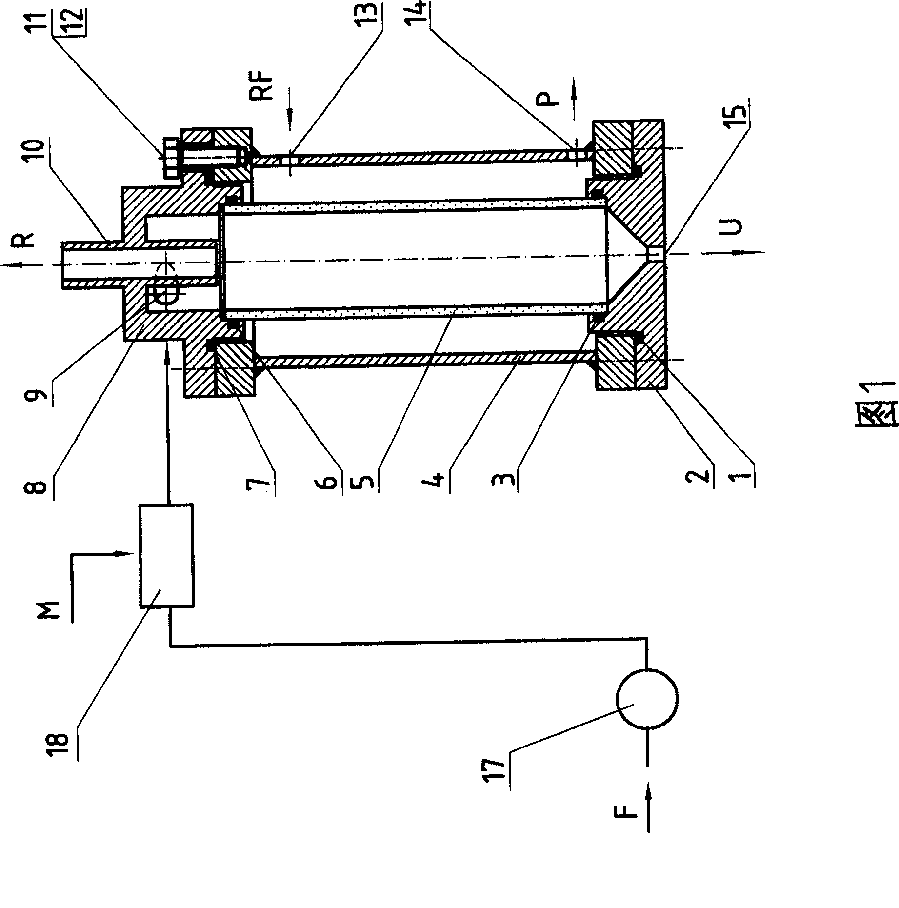
[0028] The structure of this embodiment is shown in Figure 1, which is a membrane separation device in which a membrane separation unit tube is installed in a pressure housing. In this embodiment, the membrane separation unit tube is composed of the membrane separation tube (5), the inlet part (8), the bottom flow port part (2) and the sealing parts (1, 3, 6, 7), etc., and the bolts (11) Assemble the inlet part (8) and the bottom outlet part (2) in a pressure shell (4) by welding or other methods, and the elastic ring washer (12) plays a role in preventing the bolt (11) from loosening. Here, the seal The function of (1) and (7) is to prevent the permeate fluid or recoil fluid from leaking outward through the flange, and the function of the seals (3) and (6) is to prevent the fluid in the membrane separation tube from leaking to the membrane separation tube ( 5) The space between the inner wall of the pressure shell (4) is mixed with the permeate. The shape of the pressure shel...

Embodiment 2

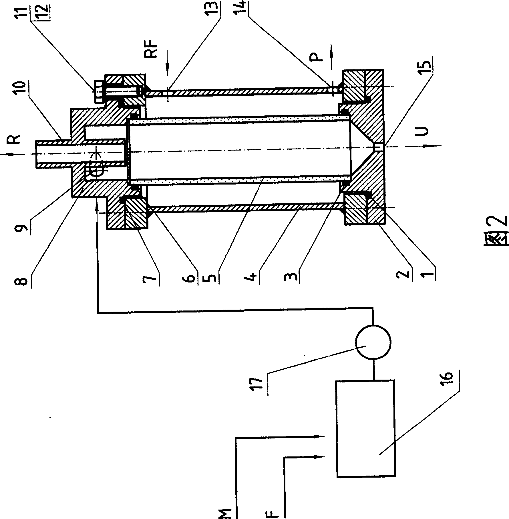
[0035] The structure of this embodiment is shown in Figure 2, which is a membrane separation device in which a membrane separation unit tube is installed in a pressure housing. In the present embodiment, its main structure is exactly the same as that of Embodiment 1, except that the mixing of the self-cleaning material and the fluid to be separated is not carried out in the mixing device (18), but in the mixing tank (preferably selecting the stirring tank) ( 16) are mixed first, and then transported to the inlet part (8) by the fluid transport machine (17), thereby constituting the membrane separation device of the present invention.

Embodiment 3

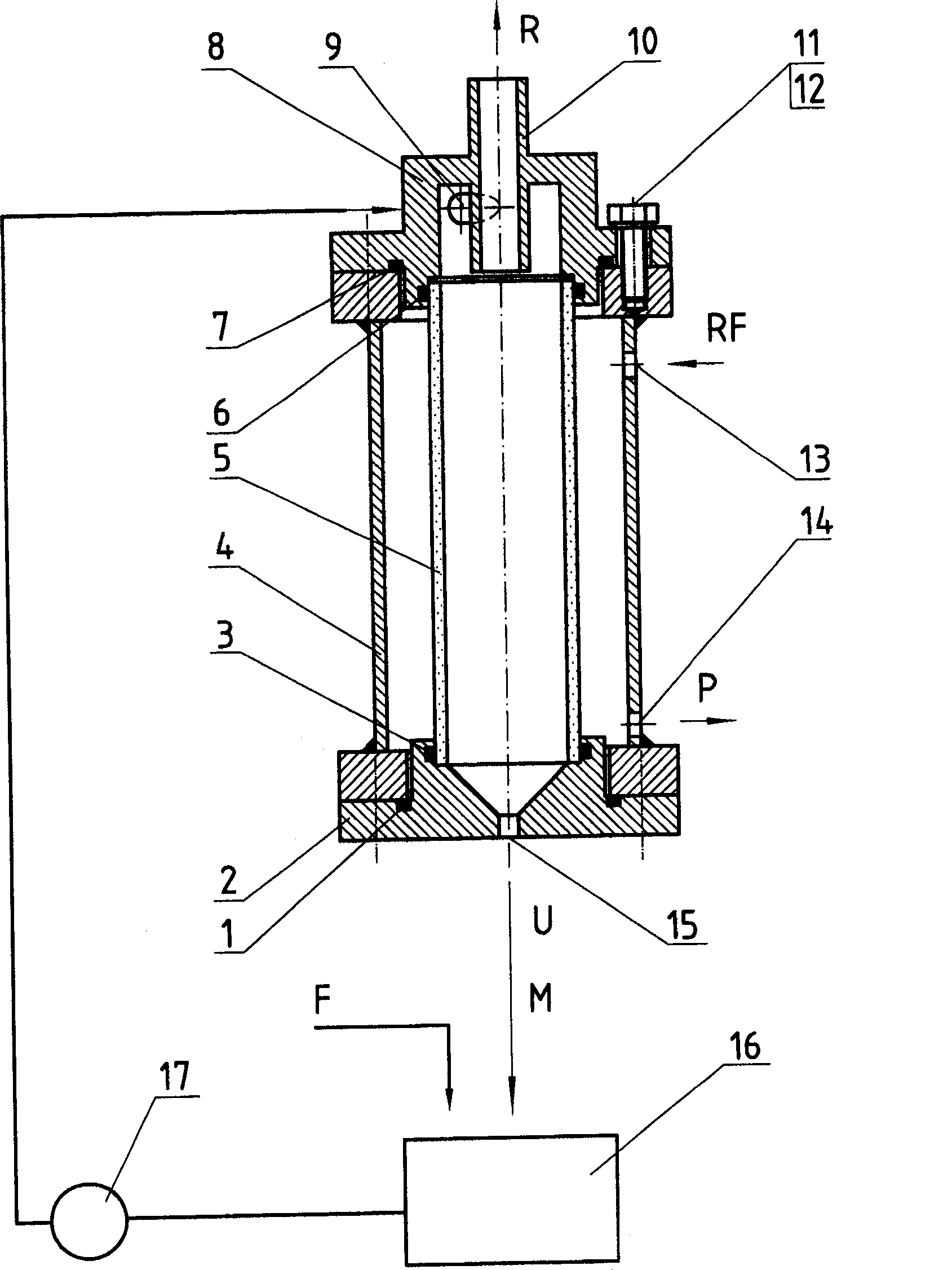
[0037] The structure of this embodiment is as attached image 3 Shown is a membrane separation device with a membrane separation unit tube installed in a pressure shell. In this embodiment, its main structure is exactly the same as that of Embodiment 1, except that the self-cleaning material is added into the mixing tank (16) in advance, and the self-cleaning material is mixed with the fluid to be separated before being transported by the fluid delivery machine (17). transported to the inlet part (8), thereby constituting the membrane separation device of the present invention. After the self-cleaning material is discharged from the bottom flow port (15) of the bottom flow port part (2), it directly enters the mixing tank (16) and mixes with fresh fluid to be separated. In this embodiment, the self-cleaning material can be recycled.


PUM

PropertyMeasurementUnit
porosityaaaaaaaaaa

Abstract

The invention unfurls a kind of separation equipment. In the shell is film separating unit tube, in front of the tube is the material of self cleaning and the equipment of the material to be separated. In the tube there is the entrance equipment of the liquid to be separated, and the flowing tube to make the liquid out and the bottom equipment to make the self material out. The liquid and the self cleaning material flow out from the flowing tube, permeating liquid goes into the film, and then goes out from the exit. Self cleaning material can move spirally along the surface of the separating film, cleaning the surface of the film continually. The invention has the advantages of proper construction, simple operation, and high effect to separate, so it can be used in industry, people and military.

Description

1. Technical field [0001] The invention relates to fluid purification equipment, in particular to microfiltration or ultrafiltration fluid purification equipment. More specifically, the present invention relates to a fluid evolution device composed of membrane separation unit tubes for fluid separation. 2. Technical background [0002] The circular tube membrane separation device has good flow state, easy control of flow rate, convenient installation and disassembly, membrane replacement and maintenance, can handle solutions containing suspended solids, and is easy to remove impurities mechanically. Appropriate flow state can reduce concentration polarization Therefore, it has broad application prospects in the fields of microfiltration and ultrafiltration. However, the data show that one of the main reasons affecting the large-scale application of membrane separation devices in practice is the membrane fouling problem. Membrane fouling not only reduces the permeation flux...

Claims


Application Information

Patent Timeline
Patent Type & Authority Patents(China)
IPC IPC(8): B04C9/00B01D35/22
Inventor 李建明陈志陈文梅
Owner SICHUAN UNIV
Why Eureka
Try Eureka