Bleed structure for a bleed passage in a gas turbine engine
- Summary
- Abstract
- Description
- Claims
- Application Information
AI Technical Summary
Benefits of technology
Problems solved by technology
Method used
Image
Examples
first embodiment
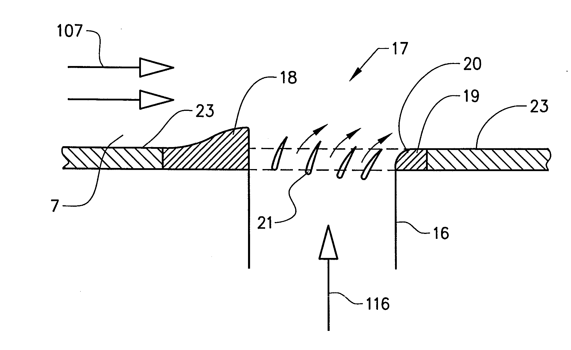
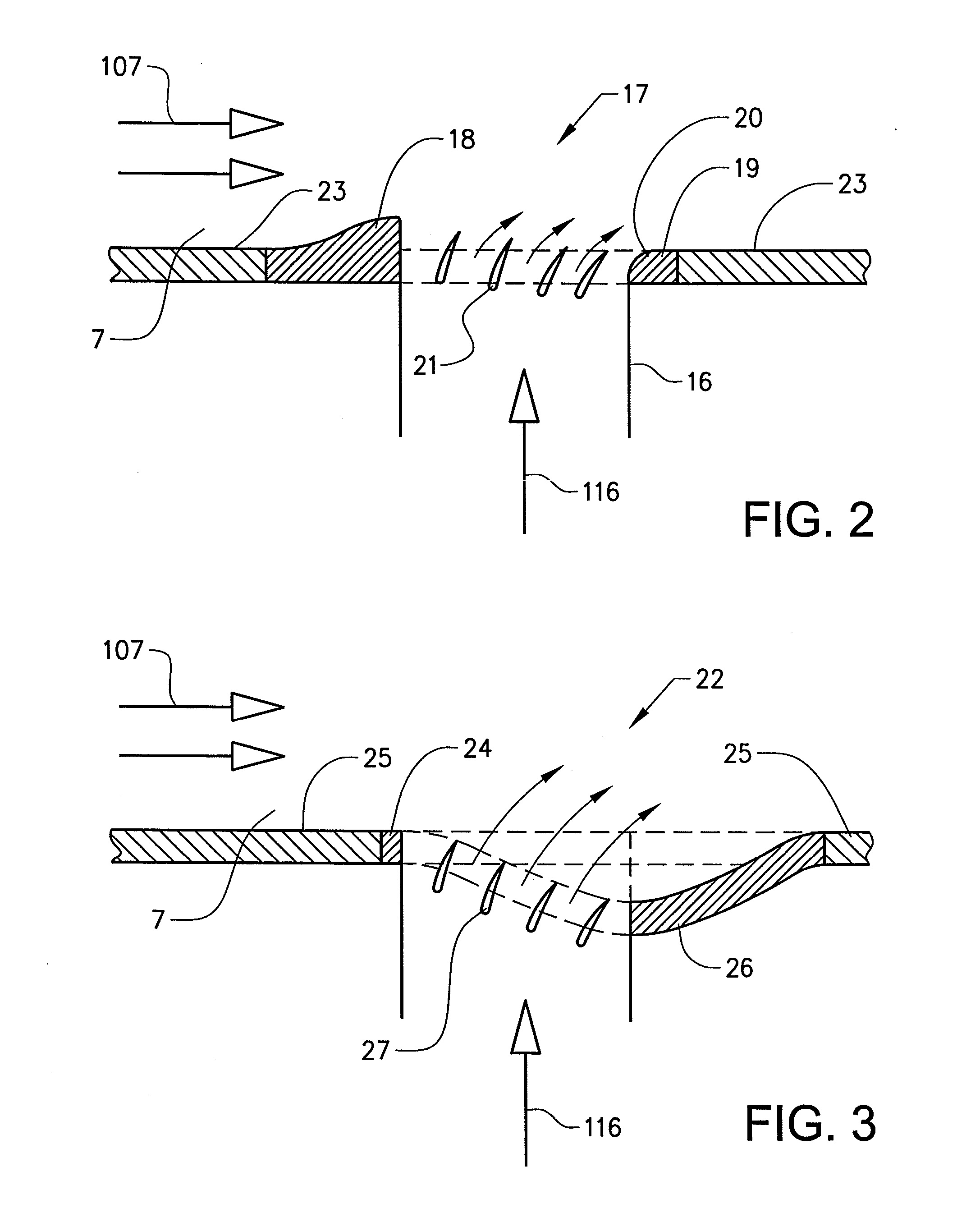
[0035]FIG. 2 shows a cut side view of a bleed structure 17 forming a bleed passage outlet to the secondary gas duct 7. The structure 17 comprises a first, upstream wall portion 18 forming a leading edge of the outlet. The structure 17 further comprises a second, downstream wall portion 19 forming a trailing edge of the outlet. The first and second wall portions 18,19 end at different distances in the extension direction of the passage 16.
[0036] The wall 23 defining the gas duct 7 is substantially at the same level across the bleed opening (outlet). Thus, the wall 23 extends along a substantially straight line across the opening.
[0037] More specifically, the upstream wall portion 18 is raised relative to the adjacent surfaces of the structure and the gas duct wall 23. Further, the upstream wall portion 18 is raised relative to the downstream wall portion 19 so that a gas flow 107 in the duct 7 is directed somewhat radially away from the outlet and thereby creating a low pressure reg...
second embodiment
[0054]FIG. 12 illustrates a bleed passage inlet structure 40. The inlet bleed structure 40 is arranged in a wall 41 defining a gas duct 42 from which gas is extracted. The structure 40 comprises a first, upstream wall portion 43 and a second, downstream wall portion 44. The upstream wall portion 43 is substantially flush with the adjacent surfaces of the structure and the gas duct wall 34. Further, an end 45 of the upstream wall portion 43 facing the inlet is chamfered defining a flow path for the bleed gas from the gas duct 42 to a bleed passage 46. The upstream wall portion 43 is smoothed and aerodynamically rounded for reducing discontinuities in the gas duct flow. A plurality of airfoils 47 are arranged in parallel to each other in the inlet for guiding a bleed gas flow from the gas duct 42.
[0055] The downstream wall portion 44 is raised relative to the adjacent surfaces of the structure and the gas duct wall 41. Further, the downstream wall portion 44 is raised relative to the ...
PUM
 Abstract
Description
Claims
Application Information
 - R&D
- Intellectual Property
- Life Sciences
- Materials
- Tech Scout
- Unparalleled Data Quality
- Higher Quality Content
- 60% Fewer Hallucinations
Browse by: Latest US Patents, China's latest patents, Technical Efficacy Thesaurus, Application Domain, Technology Topic, Popular Technical Reports.
© 2025 PatSnap. All rights reserved.Legal|Privacy policy|Modern Slavery Act Transparency Statement|Sitemap|About US| Contact US: help@patsnap.com


