
Combustion chamber intake device

A technology of air intake device and combustion chamber, which is applied in the direction of combustion engine, combustion air/combustion-air treatment, charging system, etc. It can solve the problems of volume efficiency decline and achieve the goal of increasing power density, high performance and fuel economy Effect

Inactive Publication Date: 2015-11-18
GM GLOBAL TECH OPERATIONS LLC
View PDF5 Cites 0 Cited by
  • Summary
  • Abstract
  • Description
  • Claims
  • Application Information

AI Technical Summary

Problems solved by technology

However, the use of swirl sheets will inevitably cause a decline in volumetric efficiency

Method used


Image

  • Combustion chamber intake device
  • Combustion chamber intake device
  • Combustion chamber intake device

Examples


Embodiment Construction

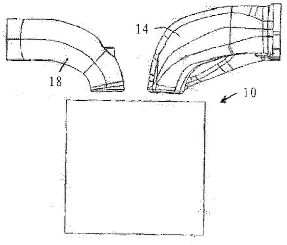
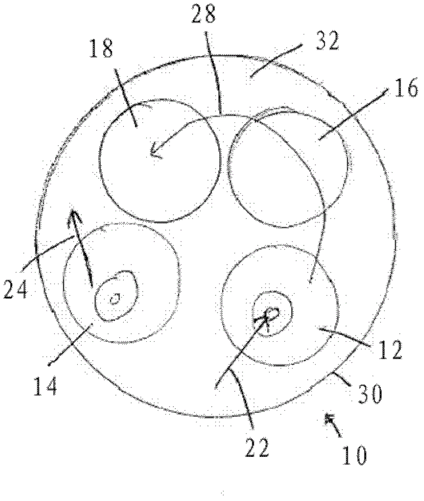
[0063] With reference to the accompanying drawings, figure 1 and 2A conventional combustion chamber or cylinder 10 of an internal combustion engine, in particular a direct injection diesel engine, is shown. In its top wall 32 , the combustion chamber includes intake ports or ducts 12 , 14 to admit air, and exhaust ports 16 , 18 . As generally indicated by arrows 22, the first air intake 12 produces a flow substantially tangential to the wall 30 of the combustion chamber to create a high degree of swirl. As generally indicated by arrow 24 , the second intake port 14 produces a flow that is directed primarily axially into the combustion chamber. However, said flow includes a non-negligible rotational or tangential component, which produces a swirling swirl in the opposite direction to the rotation of arrow 22 , which leads to an overall reduction in the value of the swirl of the combustion chamber as indicated by arrow 28 .

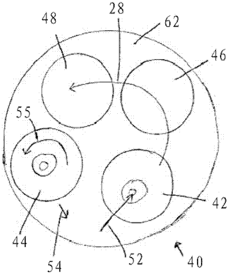
[0064] image 3 , 4 and 5 show a combustion cham...


PUM


Abstract

In an intake arrangement for a combustion chamber in which a first intake duct produces a substantially rotational flow in the chamber, the flow from a second intake duct is divided into two components. The first component is an axial flow into the chamber and the second component is a rotational flow having the same sense of rotation as the first duct. The first and second components arise from the shaping of a junction region between branches of the second intake duct adjacent the chamber.

Description

technical field [0001] The present invention relates to an air intake device for a combustion chamber, and in particular to an air intake configuration for a combustion chamber of a direct-injection diesel engine. Background technique [0002] An important aspect when designing a combustion chamber or cylinder, and the ports associated with it, is the creation of an effective region of intra-chamber motion in the form of axial swirls known as "vortices". Efficient designs create a high degree of swirl to allow rapid distribution of air or air / fuel mixture within the combustion chamber which will produce efficient combustion. [0003] Another design criterion is the discharge coefficient, which is a measure of the mass flow from the port, or the permeability of the combustion chamber, which represents how efficiently the intake port fills the combustion chamber with air or an air / fuel mixture. This is also known as engine air intake. [0004] In known four-cylinder engines,...

Claims


Application Information

Patent Timeline
Patent Type & Authority Patents(China)
IPC IPC(8): F02B23/00F02M35/104
CPCF02F1/4235F02B31/085Y02T10/146Y02T10/12F02B19/08F02B31/00F02B2031/006
Inventor L.马格罗D.麦卡罗尼
Owner GM GLOBAL TECH OPERATIONS LLC
Learn More