Range hood

a range hood and hood technology, applied in the field of kitchen appliances, can solve the problems of increased noise, reduced output, and reduced effectiveness of the system, and achieve the effect of improving the operation of the range hood

Active Publication Date: 2006-12-14
HAIER US APPLIANCE SOLUTIONS INC D B A GE APPLIANCES
View PDF96 Cites 179 Cited by
  • Summary
  • Abstract
  • Description
  • Claims
  • Application Information

AI Technical Summary

Problems solved by technology

The blower has to be large in; size, power, speed, and CFM (Cubic Feet per Minute) air movement and thus creates an increase in noise levels.
The reduction in output also reduces the ability of the system to effectively draw air into the hood and exhaust.
The resulting movement of air outside the hood results in smells, odors, steam, moisture, heat, etc. entering the work area.
The controls used presently only provide limited set points in reducing the speed of the motor.
They do not provide an unlimited range for setting the proper speed.
Moreover, “over-exhausting” may unknowingly reduce home temperatures.
It has also blown out flames in appliances and has caused air quality problems.
This makes the user have to move away from the vent opening as it is not a pleasant environment.
All blower's motors are centrally located to provide even draw for exhausting, but the flow within this design can be disrupted by any obstruction that enters the hood area including a user's arm.
Also the noise level is very high with high speed fans and to some users this level of noise is found to be objectionable.
Further, if air streams from outside sources are blowing across a range from an opened door or from a fan in the room, most range hoods cannot provide proper removal of the contaminated air.
However, this downward air movement in the front does not accomplish the desired results because air moves out of the captured zone from the sides.
The problem with this method is that as the air is moving around in a circle if a wall or an item is in the way, stoppage of movement occurs.
This stoppage results in a large area of loss entrapment for the contaminated air.
This loss then results in the contaminated air being able to escape from a large area and into the room.
These designs have been around for a long time and are unattractive for high-end units.
Such controls are also hard to clean and operate.
Also, there have been a number of fires as a result of a build up of grease / oils.
Here, the lights are often not shining in the right location when in use or if one is looking down into the cook top of the range, the user blocks the hood lights.
The use of halogen type lamps and bulbs pose other problems for cleaning.
First, cleaning and replacing is difficult.
If faulty contact is made, the life of the bulb is reduced.
The other issue with these types of designs is the ability of the user to do the cleaning and replacement from the underside of the range.
Bending over and trying to look under the range hood and clean is not easy, and therefore it is not regularly accomplished.
Another issue with using halogen lamps is the cost, which is 3 to 4 times more than an incandescent bulb.
A large number of manufacturers only provide a limited number of light levels for the user.
These limited light levels are either too bright or too dark.
The end results of the present lighting methods are generally limited.
This design does provide some removal of greases and oils, but a large amount of contaminated air still goes out the duct.
One problem is that most do not tell the user when loss of air removal has occurred.
However, this does not address the issue of loss of performance.
Thus, timing on the removal of filters for cleaning or replacement still remains an issue.
The location of heat lamps also poses an issue.
It also reduces the ability to draw contaminated air in.

Method used


Image

  • Range hood
  • Range hood
  • Range hood

Examples


Embodiment Construction

[0037] The present invention and the various features and advantageous details thereof are explained more fully with reference to the non-limiting embodiments described in detail in the following description.

1. System Overview

[0038] This invention relates to the ability to remove contaminated air, moisture, effluents, grease, heated airflows, particulates, and high temperatures and return air that is cleaned and cooled. It also addresses and provides improvement as it relates to upflow range hoods. Also on non-ducted (ductless) upflow range hoods, this invention addresses the return of heated air. This invention covers the different kinds of range hoods like island, wall, chimney, and low profile types.

2. Detailed Description of Preferred Embodiments

[0039] Various embodiments of the present invention are shown in FIGS. 1-13 which are described in additional detail below.

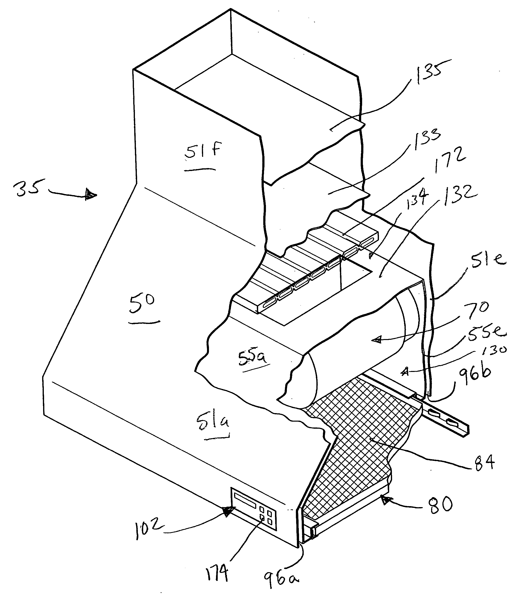
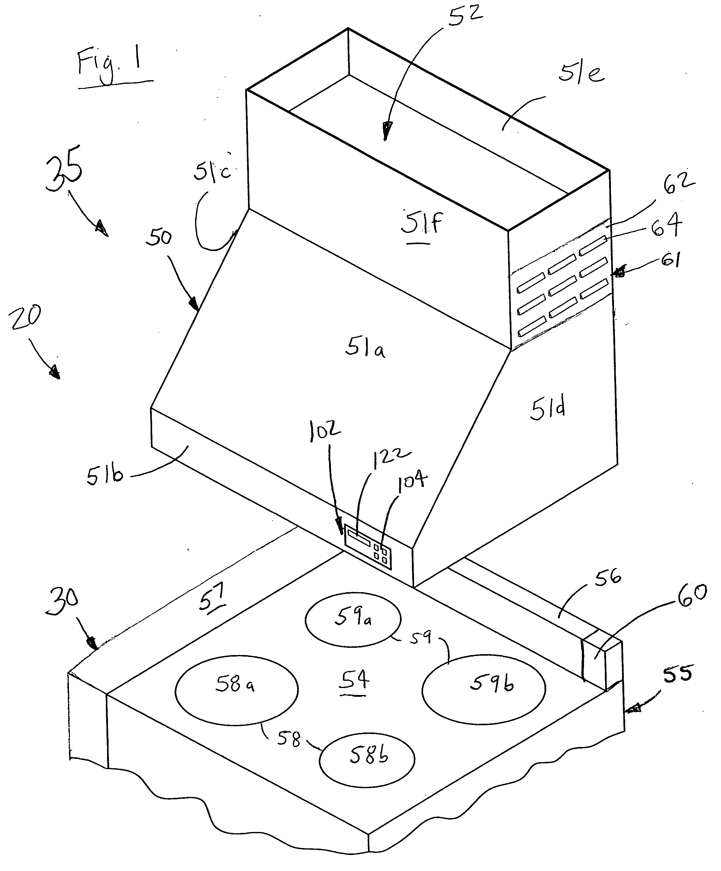
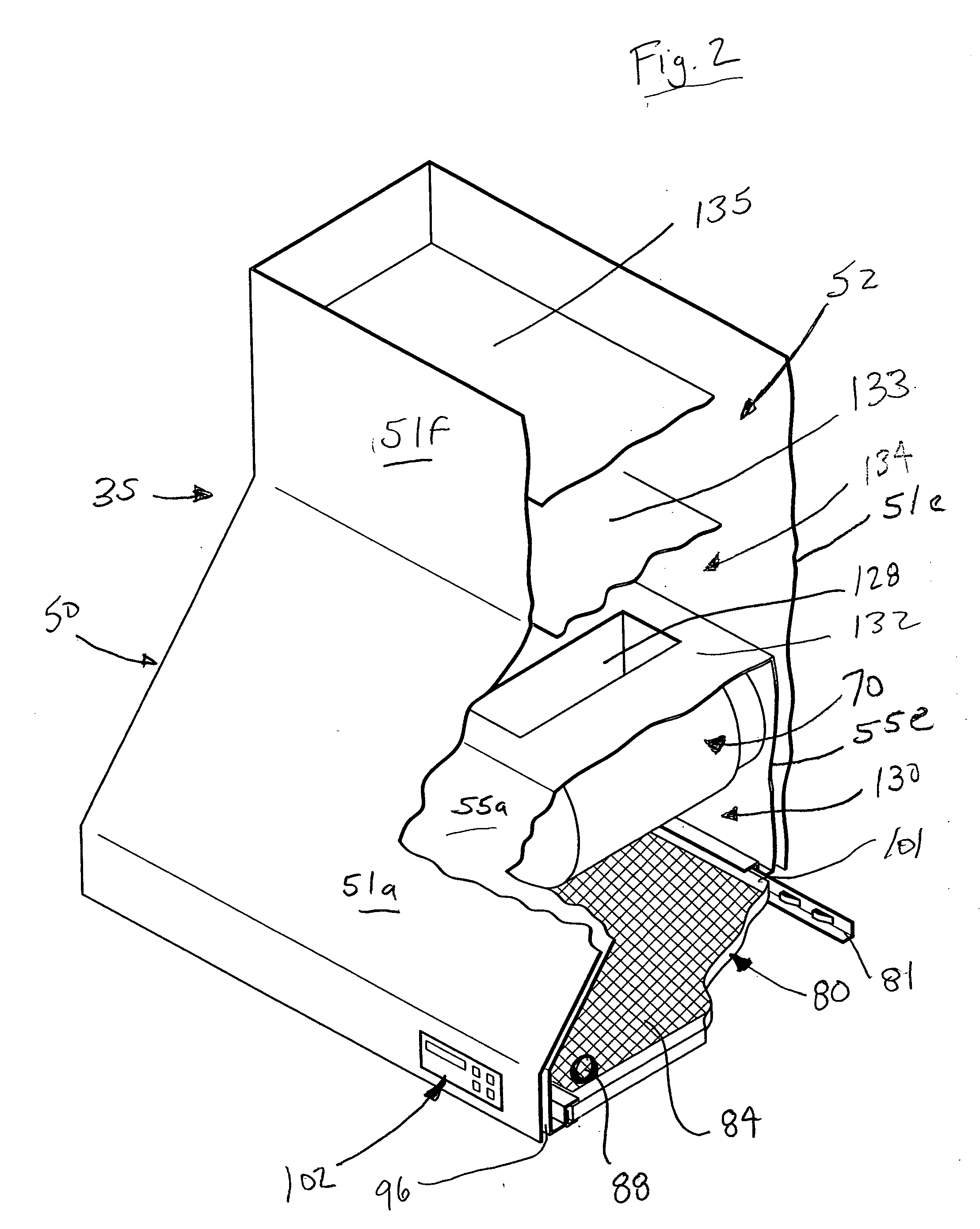
[0040]FIG. 1 shows one preferred embodiment of the appliance 20 of the present invention. In this embodimen...


PUM


Abstract

A hood for a cook top is controlled preferably by an electronic controller through a touch keypad. The hood has front and side walls and attaches to a back wall. It has an internal cavity and structure to restrict airflow out of the hood. The structure also creates an air curtain. The curtain traps and moves heated air and effluents upwardly off of the cook top. At least one blower is located near the cook top for moving the air and effluents. The hood may also have at least one: filter, sensor, duct, lighting fixture, vent, display, and circuit board.

Description

BACKGROUND OF THE INVENTION [0001] 1. Field of the Invention [0002] The present invention relates in general to the field of kitchen appliances and more particularly to an improved range hood. Specifically, a preferred embodiment of the present invention relates to a range hood having a blower located over a heating element, wherein the blower removes cooking effluents and aids in the recirculation of air toward the cook top to an air curtain around the cook top to trap the effluent. [0003] 2. Discussion of the Related Art [0004] The below-referenced U.S. patents disclose embodiments that were at least in-part satisfactory for the purposes for which they were intended. The disclosures of all the below-referenced prior United States patents in their entireties are hereby expressly incorporated by reference into the present application for purposes including, but not limited to, indicating the background of the present invention and illustrating the state of the art. [0005] U.S. Pat. ...

Claims


Application Information

Patent Timeline
Patent Type & Authority Applications(United States)
IPC IPC(8): F24C15/20
CPCF24C15/2028
Inventor GAGAS, JOHN M.STAIR, DANIEL E. IIZEIER, DAVID J.
Owner HAIER US APPLIANCE SOLUTIONS INC D B A GE APPLIANCES
Why Eureka
Try Eureka