Device and method for determining a position of a bit error in a bit sequence

a bit error and bit sequence technology, applied in the field of electrical engineering, can solve the problem that errors can be assumed to occur rather infrequently, and achieve the effect of large hardware effort and large effor

Active Publication Date: 2006-12-14
INFINEON TECH AG
View PDF6 Cites 13 Cited by
  • Summary
  • Abstract
  • Description
  • Claims
  • Application Information

AI Technical Summary

Benefits of technology

[0038] It is the object of the present invention to provide a scheme allowing to determine the position of a bit error in a received bit sequence in a simpler way, i.e. more efficient with respect to hardware and / or numerically simpler, as compared to prior art.
[0047] The present invention offers the advantage that now a numerically large effort or a large hardware effort is no longer necessary to establish which column of the check matrix matches the syndrome to identify the position of the bit error in a received bit sequence therefrom. Rather, merely by knowing the syndrome, i.e. by knowing a position of the syndrome bit in the syndrome and / or of a first bit of the syndrome bit group, a relationship, preferably a distance, between the syndrome bit and the syndrome bit group, and information on a number of rows and / or columns of a submatrix of the check matrix may be used to obtain, directly as a calculating result, the position in which the bit error has occurred, for example by applying a simple equation with an addition and a multiplication. This is particularly a result of favourably designing the check matrix.

Problems solved by technology

Often errors can be assumed to occur rather infrequently.
However, the conventional approaches of the single bit error correction have the disadvantage that, with the help of the syndrome and the check matrix, there has to be a comparison as to which column of the check matrix matches the syndrome in order to be able to determine the position of the occurred bit error therefrom.

Method used


Image

  • Device and method for determining a position of a bit error in a bit sequence
  • Device and method for determining a position of a bit error in a bit sequence
  • Device and method for determining a position of a bit error in a bit sequence

Examples


Embodiment Construction

[0052] In the following, equal or similar elements will be provided with equal or similar reference numerals, a repeated description of these elements being omitted.

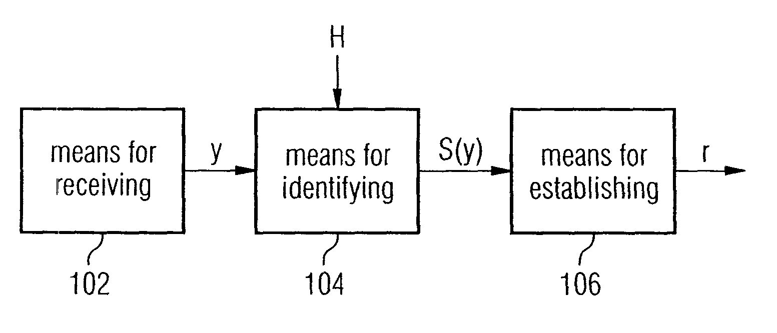
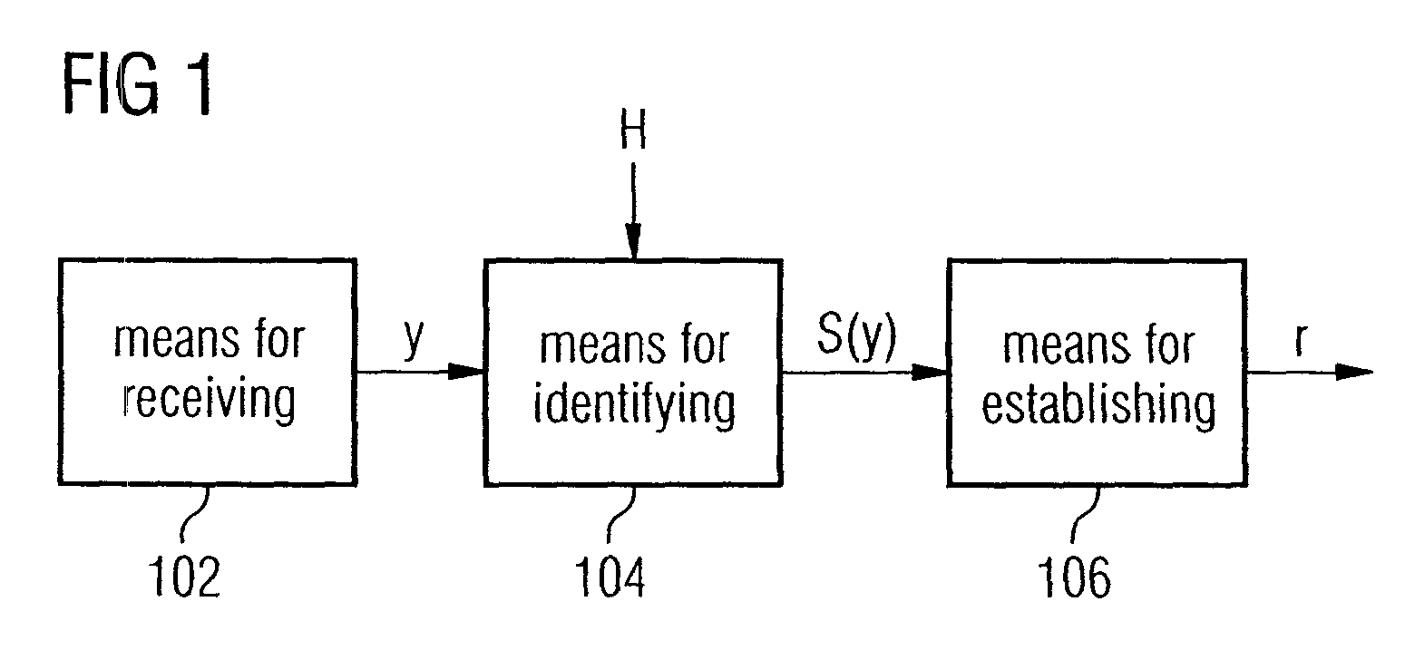
[0053]FIG. 1 shows a block circuit diagram of an embodiment of the inventive device for determining a position of a bit error in a bit sequence. The device includes means 102 for receiving a bit sequence, means 104 for identifying a syndrome S(y) and means 106 for establishing a position of a bit error in a received bit sequence. The means 102 for receiving a bit sequence may receive a bit sequence y either from a message channel or from a memory and supply this bit sequence y to the means 104 for identifying a syndrome S(y). The means 104 for identifying may identify the syndrome S(y) using the bit sequence y received from the means 102 for receiving and the check matrix H. From this syndrome S(y), the means 106 for establishing may subsequently identify the position of the bit error by merely evaluating the syndrome S...


PUM


Abstract

In a device for determining a position of a bit error in a bit sequence, a check matrix is used which has a predefined number of rows and a predefined number of columns. The check matrix includes a plurality of square submatrices having a submatrix row number and a submatrix column number corresponding to the predefined number of rows or the predefined number of columns of the check matrix. The device for determining then includes a unit for receiving a bit sequence and a unit for identifying a syndrome using the check matrix and the received bit sequence. Furthermore, the device includes a unit for establishing a position of a bit error in the received bit sequence, wherein the unit for establishing is adapted to identify a syndrome bit and a syndrome bit group in the syndrome, and wherein the unit for establishing is further adapted to determine the position of the bit error in the received bit sequence using information on a position of the syndrome bit or the syndrome bit group in the syndrome, information on a relationship between the syndrome bit and the syndrome bit group, and a submatrix row number or a submatrix column number of a submatrix.

Description

BACKGROUND OF THE INVENTION CROSS-REFERENCE TO RELATED APPLICATION [0001] This application claims priority from German Patent Application No. 10 2005 022 107.6, which was filed on May 12, 2005, and is incorporated herein by reference in its entirety. [0002] 1. Field of the Invention [0003] The present invention relates to the technical field of electrical engineering, and the present invention relates particularly to a device and a method for determining a position of a bit error in a bit sequence. [0004] 2. Description of the Related Art [0005] Errors occurring when transmitting data or storing data should be corrected as far as possible. Often errors can be assumed to occur rather infrequently. In this case, it is useful to implement a coding algorithm that is able to correct a maximum number of single bit errors in a specific data unit. [0006] The problem of the single bit error correctability is usually solved by the implementation of a suitable coding algorithm. Mostly, linear ...

Claims


Application Information

Patent Timeline
Patent Type & Authority Applications(United States)
IPC IPC(8): G06F11/00H03M13/00
CPCH03M13/19
Inventor GAMMEL, BERNDTGOETTFERT, RAINERKNIFFLER, OLIVER
Owner INFINEON TECH AG
Why Eureka
Try Eureka