Method and apparatus for packing

a technology for packaging and products, applied in the field of method and apparatus for packaging a product, can solve the problems of special problems, difficulty in maintaining the integrity of the stack, and the need for a manual restacking step

Inactive Publication Date: 2006-12-21
WELBORN KENNETH M +4
View PDF9 Cites 84 Cited by
  • Summary
  • Abstract
  • Description
  • Claims
  • Application Information

AI Technical Summary

Problems solved by technology

However, special problems are encountered when the product to be packaged comprises stacks of discrete objects.
Such stacks can be lifted manually and placed into a box, but if multiple stacks have to be placed in the same box, it can be difficult to maintain the integrity of the stacks as they are moved; this leads to the occasional need for a manual restacking step.
Furthermore, it is difficult to lift multiple adjacent stacks of objects at the same time by hand, and therefore a person would normally be limited to lifting the stacks one at a time when placing them in a box.
However, if the stacks are to be packed tightly in the box, that is, if they are to be packed with a minimal amount of space between the stacks themselves and between the stacks and the inner walls of the box, it may be difficult to manually position the stacks that are adjacent a sidewall, and especially difficult to place the last stack into a box, which stack will be bounded on four sides by box sidewalls or other stacks of products.
However, gripping a stack from the top and bottom makes it difficult to insert the stack into a previously formed box having an open top.
The upstanding walls of the matrix former, however, make it even more difficult to transfer the stacks from the matrix former to a pre-formed box or case.

Method used


Image

  • Method and apparatus for packing
  • Method and apparatus for packing
  • Method and apparatus for packing

Examples


first embodiment

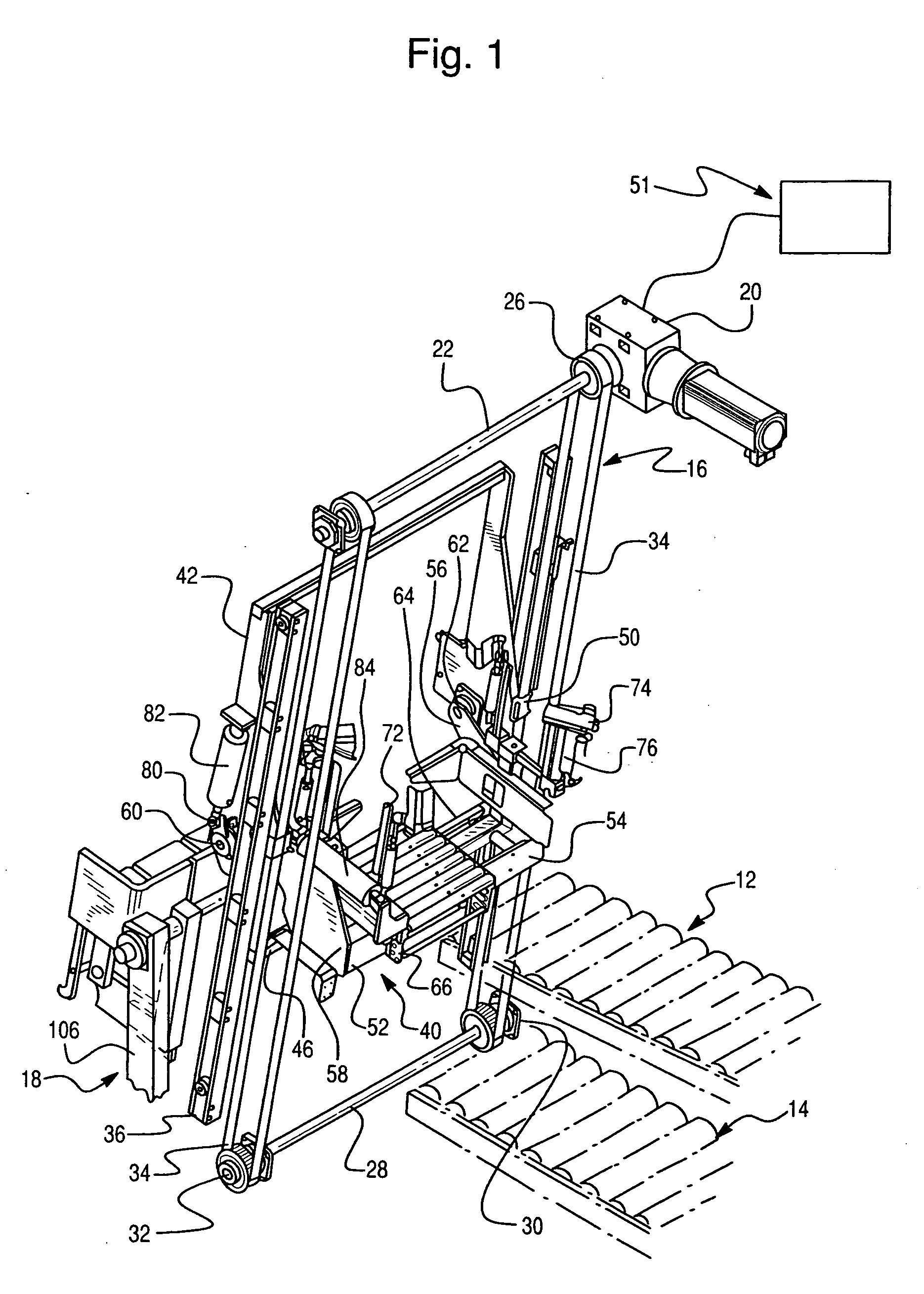
[0054] Referring now to FIGS. 1-19, wherein the showings are for the purpose of illustrating the invention only, and not for the purpose of limiting same, FIG. 1 shows a packing apparatus designated generally by the numeral 10 which includes an empty-box feeding conveyor 12, a packed-box discharge conveyor 14, a lift mechanism 16, and a matrix former 18.

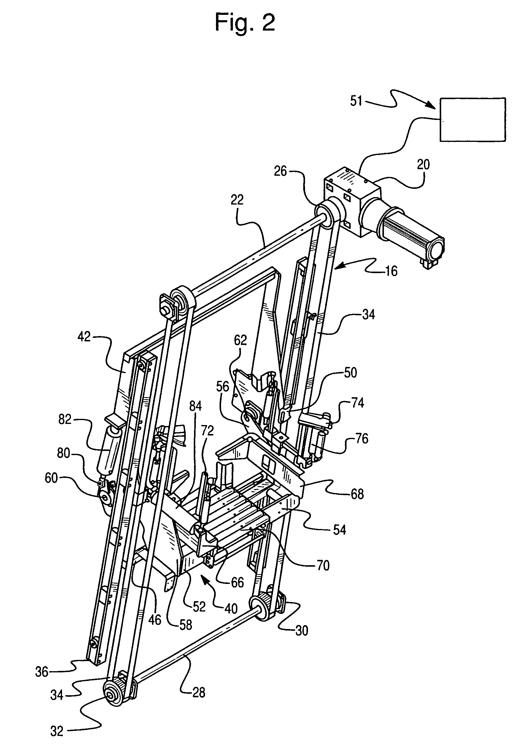
[0055] Lift mechanism 16, as best shown in FIG. 2, includes a reversible motor 20 for turning a drive shaft 22 which is supported on one end by motor 20 and on the other by a bearing 24 mounted on a support (not shown). First and second flanged wheels 26 are mounted on shaft 22 for rotation therewith, and a second shaft 28 is rotatably supported by first and second bearing plates 30 mounted to supports (not shown) parallel to the drive shaft 22. First and second flanged wheels 32 are mounted on second shaft 28 and aligned with the flanged wheels 26 on the drive shaft 22. First and second belts 34 extend between aligned pairs of flang...

second embodiment

[0069] A packing apparatus 200 is best shown in FIGS. 20 and 21. Some components of packing apparatus 200 are identical to components of packing apparatus 10, and are identified accordingly with like reference numerals. Packing apparatus 200 includes a matrix former 18, as described above, a lift assembly 202, a box rollover assembly 204, and a lowerator assembly 206.

[0070] As best shown in FIGS. 22 and 23, lift assembly 202 includes reversible motor 20 and reducer 21 for turning drive shaft 22. Drive shaft 22 is supported on one end by reducer 21 (and / or motor 20) and on the other by a bearing bracket 23 mounted to a support (not shown). First and second flanged wheels 26 are mounted on shaft 22 for rotation therewith. First and second-idle wheels 32 are mounted on first and second support brackets 208, as shown in FIG. 22. First and second idle wheels 32 are spaced from and aligned with flanged wheels 26 on drive shaft 22. First and second belts 34 extend between aligned pairs of...


PUM

PropertyMeasurementUnit
timeaaaaaaaaaa
pressureaaaaaaaaaa
movementaaaaaaaaaa

Abstract

A packing method and system are disclosed which system includes a first platform having a product support surface for supporting a product and a second platform for supporting a box into which the product is to be packed. After a box is received on and secured to the second platform, the second platform is rotated so that the open top of the box faces the first platform and moved toward the first platform until the box substantially surrounds the product on the product support surface. The first and second platforms are then rotated simultaneously so that the product is transferred from the product support to the box, and the full box is discharged to a discharge conveyor.

Description

CROSS-REFERENCE TO RELATED APPLICATIONS AND CLAIM TO PRIORITY [0001] The present application is a continuation-in-part of U.S. patent application Ser. No. 10 / 143,843, filed May 14, 2002, which claims the benefit of U.S. provisional patent application Ser. No. 60 / 290,342, filed May 14, 2001, the disclosures of which are incorporated herein by reference and to which priority is claimed.FIELD OF THE INVENTION [0002] The present invention is directed to a method and apparatus for packaging a product, and, more specifically, toward a method and apparatus for transferring a plurality of stacks of discrete objects supported by a platform from the platform to a box while maintaining the integrity and arrangement of the stacks. BACKGROUND OF THE INVENTION [0003] Various packing or packaging machines are known for placing a product into a box, carton, or other container. However, special problems are encountered when the product to be packaged comprises stacks of discrete objects. These stack...

Claims


Application Information

Patent Timeline
Patent Type & Authority Applications(United States)
IPC IPC(8): B65B5/10B65B25/06B65B35/04B65B35/50B65G57/03
CPCB65B5/06B65B5/101B65B5/106B65G2201/0205B65B35/04B65B35/50B65G57/03B65B25/065B65B5/068B65B35/30B65B39/02B65B39/12B65B43/305B65B43/52B65B43/59B65B43/60
Inventor WELBORN, KENNETH M.MARTIN, GREGG A.TOMLIN, STEVEN N.MEYER, JIMMY L.HART, COLIN R.
Owner WELBORN KENNETH M
Why Eureka
Try Eureka