Spring manufacturing apparatus

a manufacturing apparatus and spring technology, applied in forging/pressing/hammering apparatuses, forging/hammering/pressing machines, forging presses, etc., can solve the problem of difficulty in improving manufacturing precision over a certain level, and achieve the effect of more precise spring manufacturing, high precision and precise spring manufacturing

Active Publication Date: 2006-12-21
SHINKOU KIKAI INDS
View PDF5 Cites 8 Cited by
  • Summary
  • Abstract
  • Description
  • Claims
  • Application Information

AI Technical Summary

Benefits of technology

[0007] The present invention has been conceived in view of the foregoing situation, with an object to provide a spring manufacturing apparatus in which the first bending dice mounting slider is linked with the other bending dice mounting sliders thus to reduce the number of driving sources, and which is capable of adjusting the relative positions among the bending dices with higher precision, when manufacturing a spring.
[0021] The structure according to the third aspect permits causing the bending dice to linearly move upward or downward by a predetermined angle, together with the first bending dice mounting slider which is not provided with the driving source, by the swinging motion of the swinging member, resulting in more precise manufacturing of springs in various shapes.

Problems solved by technology

Accordingly, the other bending dice mounting sliders cannot be moved at the same speed as the first bending dice mounting slider, and therefore it is difficult to improve manufacturing precision over a certain level when manufacturing a spring with a variable outer diameter.

Method used


Image

  • Spring manufacturing apparatus
  • Spring manufacturing apparatus
  • Spring manufacturing apparatus

Examples


Embodiment Construction

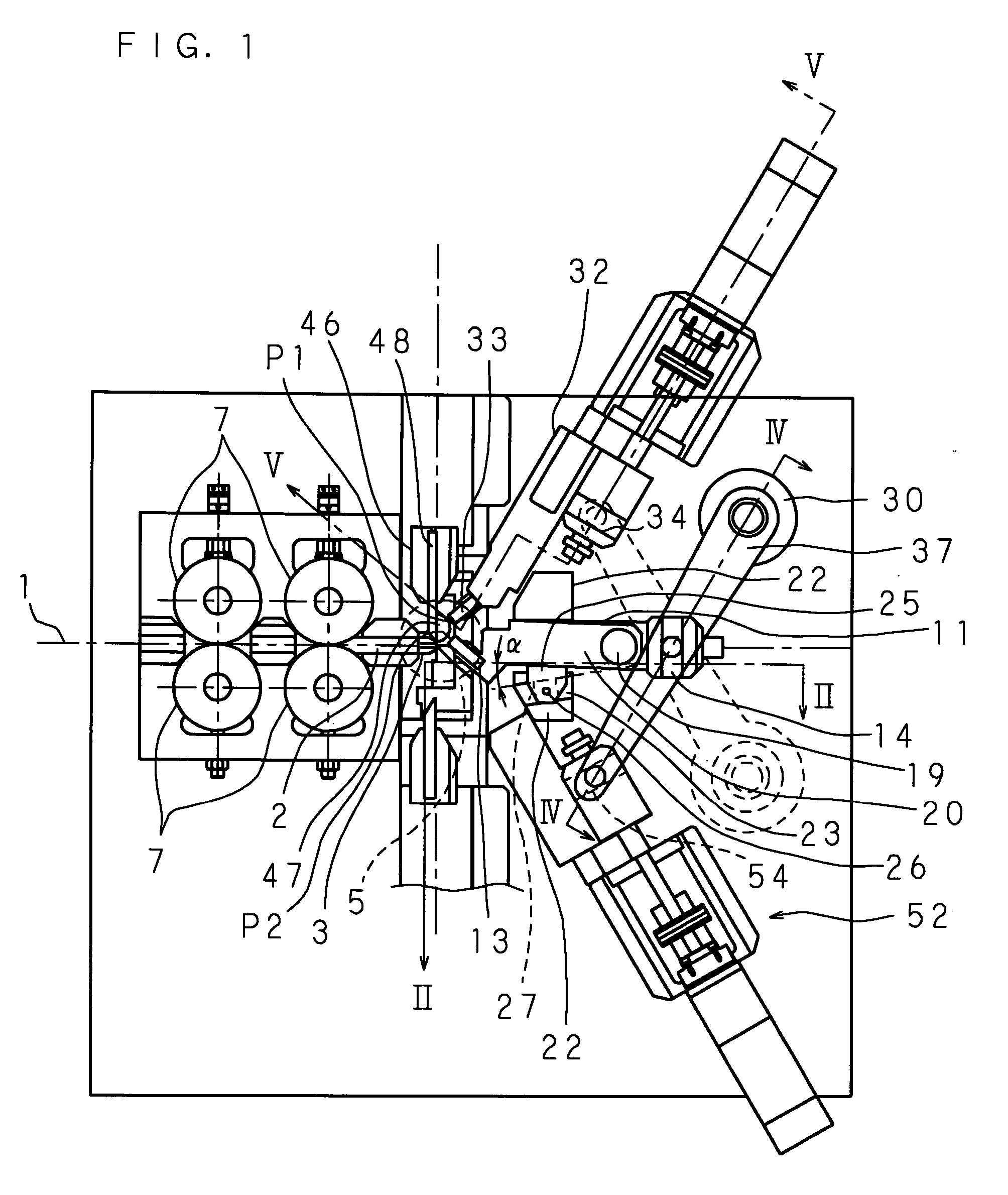
[0030] Hereunder, the present invention will be described based on the drawings showing an embodiment thereof. FIG. 1 is a front view showing a main portion of a spring manufacturing apparatus according to an embodiment of the present invention.

[0031] As shown in FIG. 1, in the spring manufacturing apparatus according to the embodiment, a wire 1 is led to two pairs of wire feeding rollers 7, 7, . . . each including an upper and a lower roller. In the wire feeding rollers 7, 7, . . . , the upper rollers 7, 7 rotate counterclockwise, and the lower rollers 7, 7 rotate clockwise, thus to feed the wire 1 to the wire path 2.

[0032] The wire 1 led to an end portion of the wire path 2 is introduced to a wire processing space 5, to be butted to, for example, bending dices 13, 33 mounted on a tip portion of a first bending dice mounting slider 11 and a second bending dice mounting slider 32, respectively. The wire 1 is bent and deformed in a desired direction according to an angle and relati...


PUM

PropertyMeasurementUnit
shapeaaaaaaaaaa
outer diameteraaaaaaaaaa
rotation radiusaaaaaaaaaa

Abstract

A spring manufacturing apparatus with a reduced number of driving sources, yet capable of adjusting the relative positions among the bending dices with higher precision when manufacturing a spring is to be provided. A second bending dice mounting slider and a third bending dice mounting slider are symmetrically located about a center line extended from a moving direction of a first bending dice mounting slider. An arm mechanically connects the first bending dice mounting slider and the second bending dice mounting slider, or the first bending dice mounting slider and the third bending dice mounting slider, so that either of a driving source that drives the second bending dice mounting slider or a driving source that drives the third-bending dice mounting slider moves the first bending dice mounting slider, thus to determine a winding direction of a wire for manufacturing a spring.

Description

CROSS-REFERENCE TO RELATED APPLICATIONS [0001] This Nonprovisional application claims priority under 35 U.S.C.§119(a) on Patent Application No. 2005-181017 filed in Japan on Jun. 21, 2005, the entire contents of which are hereby incorporated by reference. BACKGROUND OF THE INVENTION [0002] The present invention relates to a spring manufacturing apparatus with a reduced number of driving sources, yet capable of precisely bending the spring. [0003] A conventional spring manufacturing apparatus has a wire processing space where the wire is formed into a spring, defined by a front wall of a casing. The spring manufacturing apparatus includes at least a pair of wire feeding rollers that delivers the wire to the wire processing space, via a wire path. The wire fed into the wire processing space is bent by a bending dice mounted on three bending dice mounting sliders, installed so as to move into and out of the wire processing space. [0004] The three bending dice mounting sliders are locat...

Claims


Application Information

Patent Timeline
Patent Type & Authority Applications(United States)
IPC IPC(8): B21F3/02
CPCB21F35/00B21F3/02
Inventor TSURITANI, KATSUHIDE
Owner SHINKOU KIKAI INDS
Why Eureka
Try Eureka