Remote control lighting control system

a remote control and lighting technology, applied in the field of remote control systems, can solve the problems of affecting the consumer and the market, affecting the programming/configuration requirements placed on the user of prior art remote control systems, and consuming time,

Active Publication Date: 2006-12-21
LUTRON TECH CO LLC
View PDF20 Cites 116 Cited by
  • Summary
  • Abstract
  • Description
  • Claims
  • Application Information

AI Technical Summary

Benefits of technology

[0024] According to a first embodiment of the present invention, a system for remotely controlling at least two electrical devices comprises a master control unit and at least two control devices. The master control unit is operable to transmit signals containing control information for controlling the electrical devices. The at least two control devices are operable to receive the signals from the master control unit. Each of the control devices is respectively electrically connected to at least one of the electrical devices and is responsive to the control information for controlling the at least one of the electr

Problems solved by technology

Although the prior art remote systems function to integrate with prior art switches and to provide remote control of electrical devices, various shortcomings and inconveniences exist which negatively impact the consumer and the market.
The programming/configuration requirements placed on a user of prior art remote control systems are considered fairly complex, and in order to assist the user with configuration and programming, prior art systems may be distributed with a hand-written programming worksheet to be used by the user to set up or change the configuration of a system.
It is believed by the inventors that configuring prior art remote control systems can be tedious, complicated, and time-consuming, particularly for members of the residential retail market.
Many consumers find prior art remote control systems simply too complicated to install and configure, and, accordingly, do not invest in remote control systems, notwithstanding the convenience and enjoyment such systems ultimately provide.
Furthermore

Method used


Image

  • Remote control lighting control system
  • Remote control lighting control system
  • Remote control lighting control system

Examples


Embodiment Construction

[0039] The foregoing summary, as well as the following detailed description of the preferred embodiments, is better understood when read in conjunction with the appended drawings. For the purposes of illustrating the invention, there is shown in the drawings an embodiment that is presently preferred, in which like numerals represent similar parts throughout the several views of the drawings, it being understood, however, that the invention is not limited to the specific methods and instrumentalities disclosed.

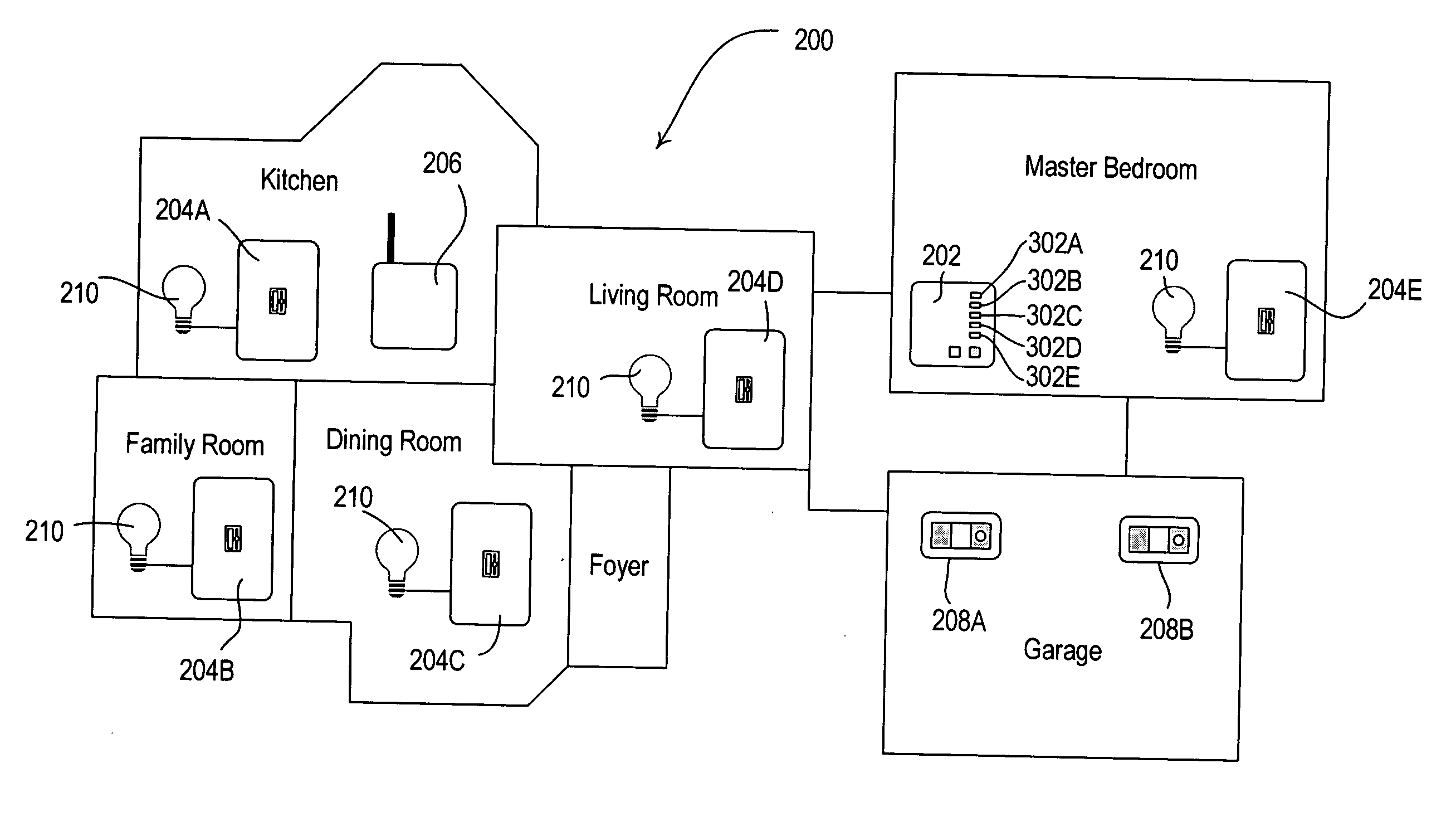
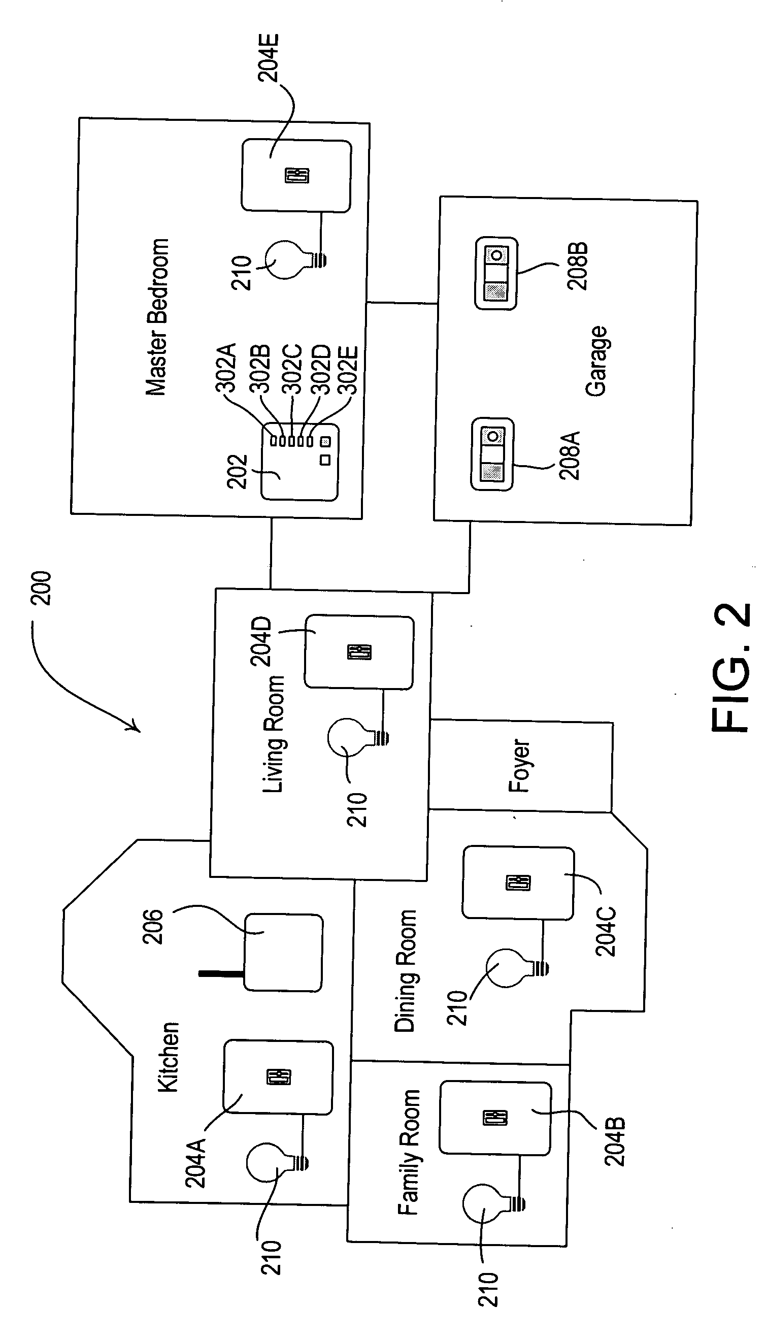
[0040] According to one aspect, the present invention is directed to a wireless radio frequency (RF) control system for controlling electrical devices, for example installed in a building structure such as a residential home, and made available in a retail market. In a preferred embodiment, a remotely and manually controllable control device replaces a conventional mechanical electrical switch, and operates without requiring setup and / or configuration by a user thereby reducin...


PUM


Abstract

A two-way radio frequency lighting control system comprises a master control including a plurality of manual actuators, and a plurality of dimmers, in which the number of dimmers does not exceed the number of manual actuators. After the lighting control system is installed in an intended end user location, and prior to the first time the lighting control system is energized in the intended end user location, each of the manual actuators is operative to affect the status of one, and only one, of the plurality of dimmers. A turn key lighting control system in which there is a one-to-one correspondence of manual actuators to dimmers is thereby provided.

Description

RELATED APPLICATIONS [0001] This application claims priority from commonly-assigned U.S. Provisional Application Ser. No. 60 / 687,894, filed Jun. 6, 2005, having the same title as the present application, the entire disclosure of which is hereby incorporated by reference.BACKGROUND OF THE INVENTION [0002] 1. Field of the Invention [0003] The present invention relates, generally, to remote control systems, and, more particularly, to a pre-programmed radio frequency (RF) control system and method for controlling one or more lighting controls. [0004] 2. Description of the Related Art [0005] Systems for controlling an electrical device by remote control are known. For example, prior art systems and methods control the status of electrical devices such as electric lamps, from a remote location via communication links, including radio frequency links, power line carrier links or infrared links. Status information regarding the electrical devices (e.g., on, off and intensity level) is typic...

Claims


Application Information

Patent Timeline
IPC IPC(8): G06F13/42
CPCH05B37/0272H01Q7/005H05B47/195
Inventor NEWMAN, ROBERT C. JR.
Owner LUTRON TECH CO LLC
Why Eureka
Try Eureka