
Optical system and optical apparatus having the same

a technology applied in the field of optical system and optical apparatus, can solve the problems of difficult to correct chromatic aberration over the entire picture, difficult to correct various aberrations in a well-balanced state, and difficult to correct both chromatic aberration and various aberrations, so as to facilitate the correction and/or reduction of various aberrations

Active Publication Date: 2006-12-21
CANON KK
View PDF6 Cites 36 Cited by
  • Summary
  • Abstract
  • Description
  • Claims
  • Application Information

AI Technical Summary

Benefits of technology

[0015] According to an aspect of the present invention, an optical system facilitates correcting and / or reducing various aberrations including chromatic aberration.

Problems solved by technology

In particular, in a Gauss-type optical system and a modified Gauss-type optical system, such as a Xenoter type and an ortho-meter type, in that lenses are arranged roughly symmetrically with respect to an aperture diaphragm, since an F number is comparatively small (bright) as well as an angle of view is comparatively large, it has been difficult to correct chromatic aberration over the entire picture while suppressing various aberrations including spherical aberration, coma, and astigmatism.
However, it can be difficult to correct various aberrations in a well-balanced state using the extraordinary partial dispersion material in optical systems other than this optical system.
Therefore, it can be difficult to correct both the chromatic aberration and the various aberrations such as the spherical aberration, the coma, and the astigmatism.
On the other hand, although the diffractive optical element has a sufficient correction function of the chromatic aberration, unnecessary diffraction light in the order of diffraction other than that designed for practical use is generated.
Since the material discussed in U.S. Pat. Nos. 5,731,907 and No. 5,638,215 is liquid, when it is used as an optical material, the manufacturing is difficult because of the necessity of the structure for sealing it.
Also, characteristics, such as the refracting index and the dispersion, are largely changed with the change in temperature, so that the environmental resistance is insufficient.
Furthermore, the interface to air is not obtained, so that the chromatic aberration is difficult to be sufficiently corrected.

Method used


Image

  • Optical system and optical apparatus having the same
  • Optical system and optical apparatus having the same
  • Optical system and optical apparatus having the same

Examples


numerical example 6

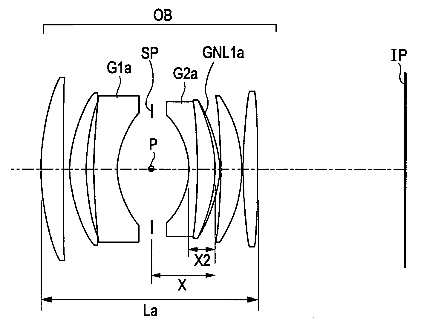
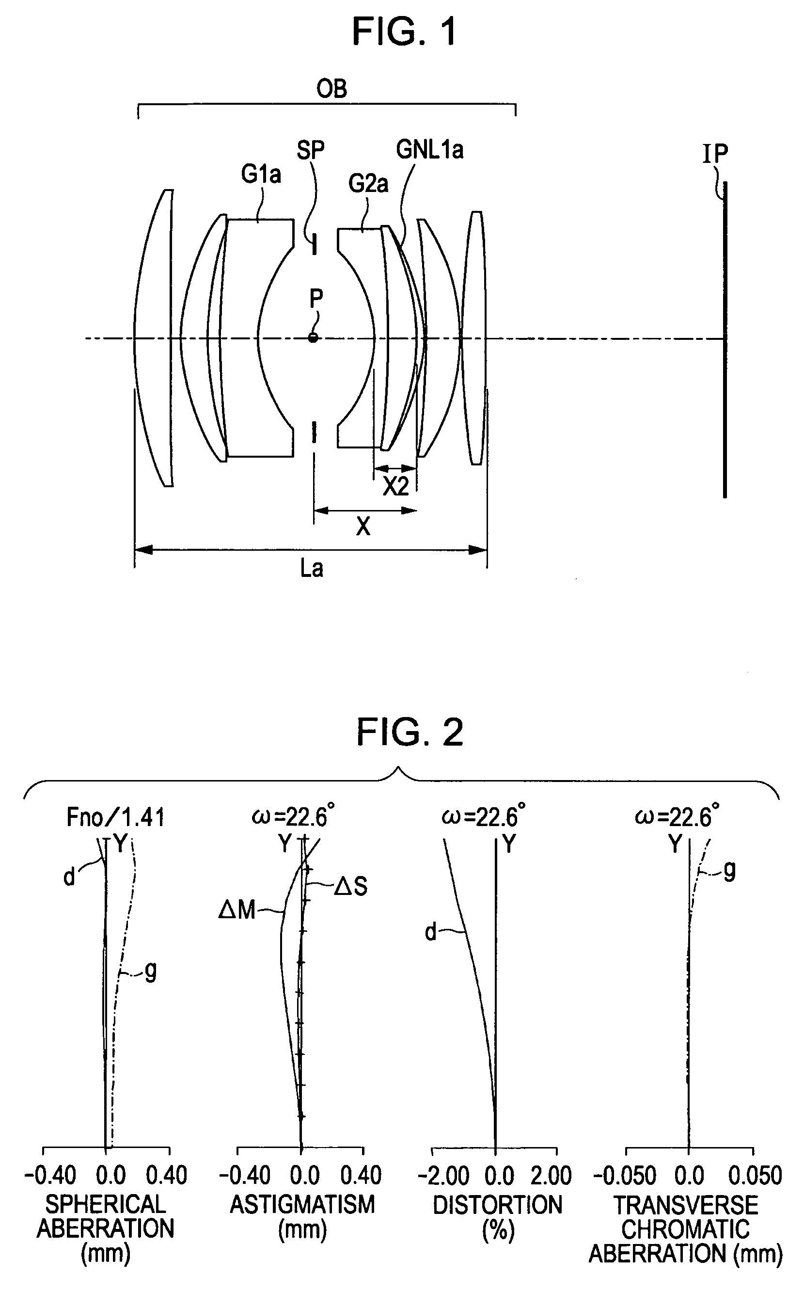
[0179]FIG. 11 is a lens sectional view of an optical system of a numerical example 6, in which the refractive optical element GNL1f, as a refractive optical part made of, for example, a mixture of TiO2 fine particles dispersed into the UV-curing resin 2, is used in a Gauss-type optical system with about a 50 mm focal length and about a 1.8 F number. Reference character SP denotes an aperture-stop. FIG. 12 is an aberration drawing of the optical system of the numerical example 6 in an in-focus state of an object at infinity.

[0180] In the optical system of the numerical example 6, by introducing a lens of the refractive optical element GNL1f made of, for example, dispersed TiO2 fine particles in the vicinity of the aperture-stop SP, the axial chromatic aberration is mainly well-corrected.

NUMERICAL EXAMPLE 7

[0181]FIG. 13 is a lens sectional view of an optical system of a numerical example 7, in which the refractive optical element GNL1g, as a refractive optical part made of, for exa...

numerical example 1

[0200]

f = 51.8 Fno = 1.41 2ω = 45.2°R1 = 54.846D1 = 4.74N1 = 1.8388ν1 = 44.3R2 = 1059.047D2 = 1.50R3 = 30.372D3 = 3.56N2 = 1.8850ν2 = 41.0R4 = 49.954D4 = 1.71R5 = 132.860D5 = 4.99N3 = 1.6766ν3 = 29.9R6 = 19.377D6 = 7.49R7 = ∞ (STOP)D7 = 8.19R8 = −17.653D8 = 1.80N4 = 1.8442ν4 = 23.5R9 = −149.083D9 = 3.91N5 = 1.6604ν5 = 56.8R10 = −31.705D10 = 1.00NGNL1 = 1.6356νGNL1 = 22.7R11 = −26.006D11 = 0.15R12 = −124.728D12 = 4.66N6 = 1.8813ν6 = 41.2R13 = −30.469D13 = 0.15R14 = 104.212D14 = 3.29N7 = 1.7800ν7 = 50.0R15 = −226.181

numerical example 2

[0201]

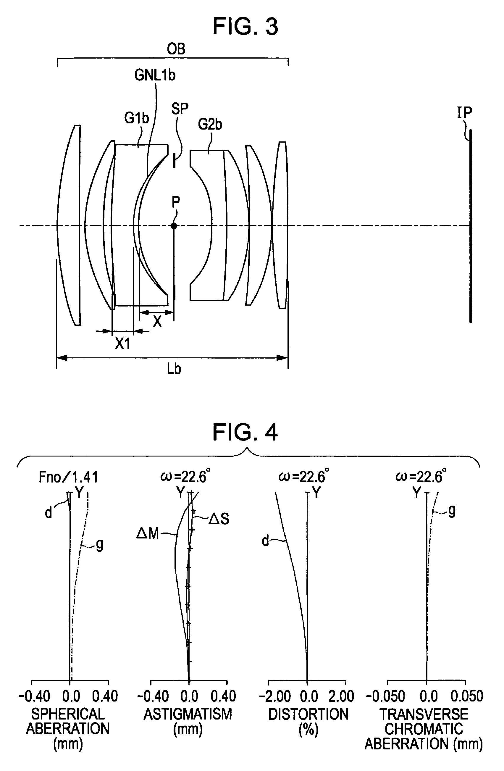
f = 51.8 Fno = 1.41 2ω = 45.2°R1 = 57.969D1 = 4.76N1 = 1.7951ν1 = 48.3R2 = −2707.826D2 = 1.37R3 = 31.136D3 = 3.60N2 = 1.8850ν2 = 41.0R4 = 53.389D4 = 1.76R5 = 171.615D5 = 4.30N3 = 1.6636ν3 = 30.8R6 = 18.045D6 = 1.00NGNL1 = 1.5912νGNL1 = 31.7R7 = 20.535D7 = 7.32R8 = ∞ (STOP)D8 = 8.09R9 = −18.791D9 = 2.56N4 = 1.8610ν4 = 26.8R10 = −355.861D10 = 4.97N5 = 1.7368ν5 = 52.0R11 = −28.736D11 = 0.15R12 = −146.911D12 = 4.43N6 = 1.8815ν6 = 41.2R13 = −32.915D13 = 0.15R14 = 100.019D14 = 3.19N7 = 1.7800ν7 = 50.0R15 = −296.6298


PUM


Abstract

At least one exemplary embodiment is directed to an optical system which includes a plurality of refractive optical elements arranged substantially symmetrically with respect to an aperture-stop. Furthermore the optical system comprises a refractive optical element being constituted by a solid material. An Abbe number νd of the solid material and a partial dispersion ratio θgF of the solid material can satisfy the following conditions:θgF−(−1.665×10⁻⁷·νd3+5.213×10⁻⁵·νd2−5.656×10⁻³·νd+0.755)>0,θgF−(−1.665×10⁻⁷·νd3+5.213×10⁻⁵·νd2−5.656×10⁻³·νd+1.011)<0.

Description

BACKGROUND OF THE INVENTION [0001] 1. Field of the Invention [0002] The present invention relates to an optical system and an optical apparatus having the optical system. [0003] 2. Description of the Related Art [0004] In general, in the optical system used in optical apparatuses including digital cameras, video cameras, and copying machines, as the miniaturization of the entire optical system is extended by reducing the entire lens length (the entire length of the optical system, which is the distance between the first lens surface adjacent to the object and the image plane), the more chromatic aberration including axial chromatic aberration and transverse chromatic aberration (chromatic aberration of magnification) is generated so as to have a tendency to reduce optical performances. [0005] In particular, in a Gauss-type optical system and a modified Gauss-type optical system, such as a Xenoter type and an ortho-meter type, in that lenses are arranged roughly symmetrically with re...

Claims


Application Information

Patent Timeline
IPC IPC(8): G02B9/08
CPCG02B13/0035G02B13/004G02B13/009G02B13/006G02B13/0045
Inventor KOBAYASHI, MIKIO
Owner CANON KK
Learn More