Switching Control Circuit and Self-Excited DC-DC Converter

a control circuit and self-excitation technology, applied in the direction of electric variable regulation, process and machine control, instruments, etc., can solve the problems of a circuit on the load side that cannot the output voltage vout changes, and the circuit cannot be quickly output the output, etc., to reduce the level of comparison voltage

Active Publication Date: 2006-12-28
SEMICON COMPONENTS IND LLC +1
View PDF4 Cites 29 Cited by
  • Summary
  • Abstract
  • Description
  • Claims
  • Application Information

AI Technical Summary

Benefits of technology

The present invention provides a switching control circuit for a self-excited DC-DC converter that can generate an output voltage of a target level that is different from the level of the input voltage. The circuit includes a switching control signal generation circuit that detects a change in ripples of the output voltage and generates a switching control signal for the on/off control of the switching element to make the output voltage follow the target level, an overcurrent protection signal generation circuit that detects the output current of the self-excited DC-DC converter and, when it is detected that the output current is in an overcurrent state where being equal to a predetermined current or greater, generates an overcurrent protection signal for turning off the switching element to make the output current less than the predetermined current regardless of the switching control signal, and an output correction circuit that adjusts the comparison voltage according to a relative error of the feedback voltage with respect to the reference voltage to make the average level of the feedback voltage coincide with the reference voltage corresponding to the target level, and when the overcurrent protection signal generation circuit detects that the output current is in the overcurrent state, reduces the level of the comparison voltage.

Problems solved by technology

The technical problem of the patent text is to solve the deviation in the output voltage of a ripple converter caused by the overcurrent protection mechanism and to improve the accuracy of the output voltage. The solution involves introducing an output correction circuit with an error amplifier and a divided voltage that can adjust the average level of the divided voltage to match the reference voltage. However, the conventional overcurrent protection circuit has a problem of overshooting the output voltage after the overcurrent protection is released.

Method used


Image

  • Switching Control Circuit and Self-Excited DC-DC Converter
  • Switching Control Circuit and Self-Excited DC-DC Converter
  • Switching Control Circuit and Self-Excited DC-DC Converter

Examples


Embodiment Construction

[0053] From the contents of the description and the accompanying drawings, at least the following details will be apparent.

[0054]

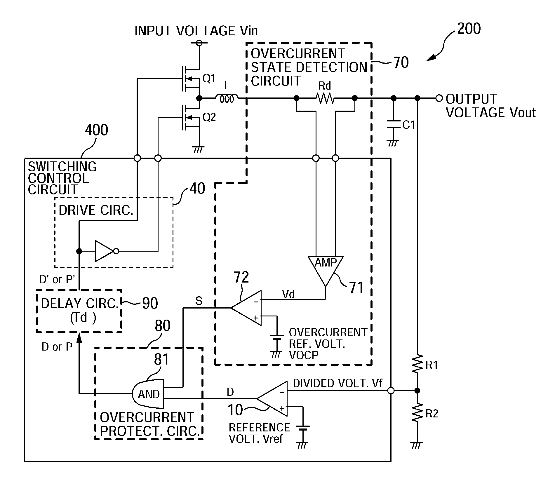
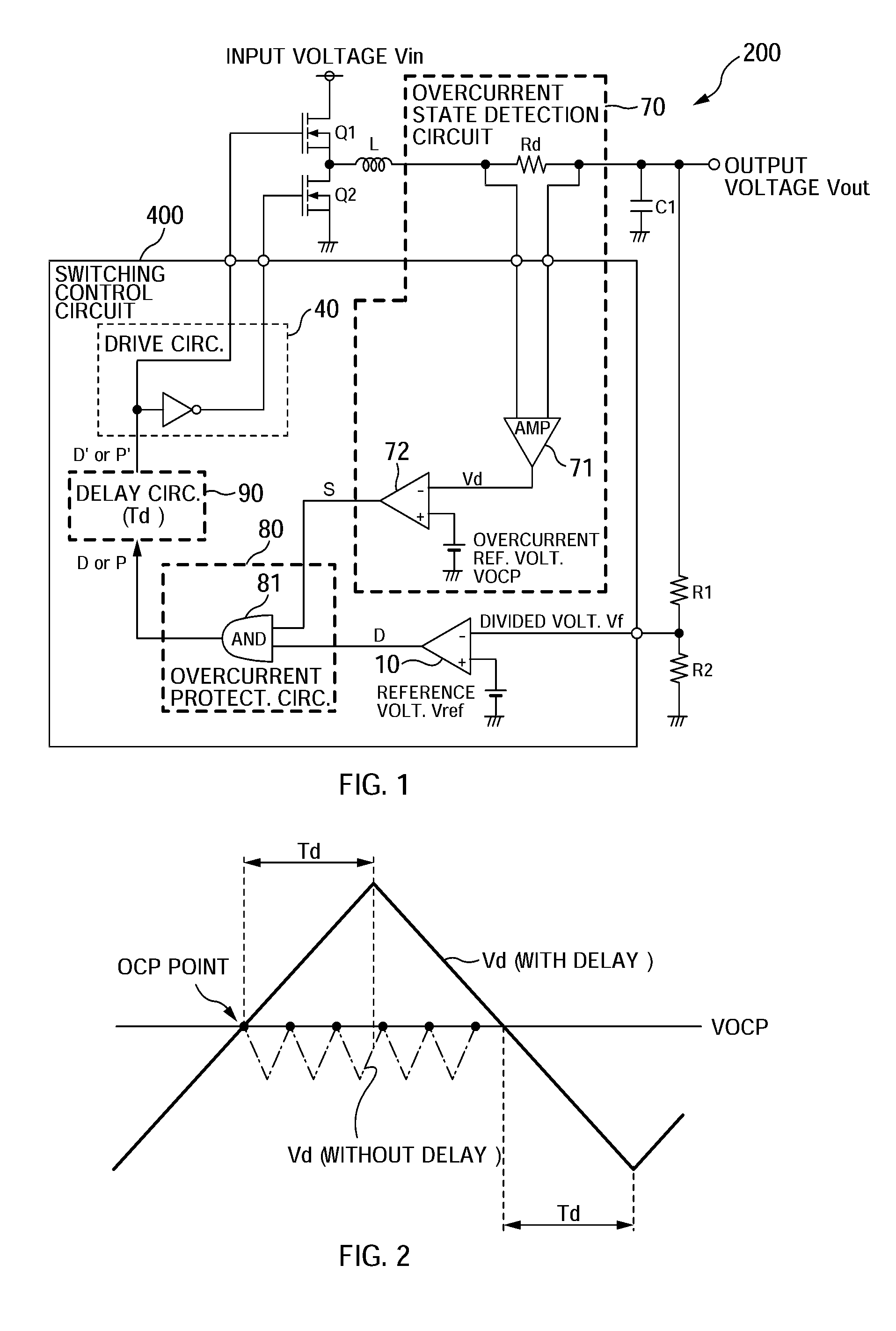
[0055] ==Configuration of Ripple Converter Using Switching Control Circuit==

[0056]FIG. 1 shows a ripple converter 200 having external components connected to a switching control circuit 400 that is an integrated circuit provided with an overcurrent protection mechanism according to a first implementation of the present invention.

[0057] In this implementation, the external components of the switching control circuit 400 are a switching element that is a serial connection body of NMOS transistors Q1, Q2, a LC smoothing circuit constituted by a smoothing coil L and a capacitance element Cl, a dividing circuit that is a serial connection body of resistance elements R1, R2, and a resistance element Rd for detecting an output current Iout corresponding to an output voltage Vout. In some implementations, the external components may be built into the switching c...


PUM


Abstract

A self-excited DC-DC converter comprises a switching element that chops a direct-current input voltage; a smoothing circuit that smoothes the chopped voltage to generate a DC output voltage; a switching control signal generation circuit that generates a switching control signal for the on/off control of the switching element by comparing a feedback voltage of the output voltage and a comparison voltage; an output correction circuit that adjusts the comparison voltage according to an error between the feedback voltage and the reference voltage and, when the output current is in the overcurrent state, reduces the level of the comparison voltage; an overcurrent protection signal generation circuit that, when the output current is in an overcurrent state, generates an overcurrent protection signal for turning off the switching element regardless of the switching control signal; and a delay circuit that delays the overcurrent protection signal. Also, a switching control circuit is provided therein.

Description


Claims


Application Information

Patent Timeline
Owner SEMICON COMPONENTS IND LLC
Why Eureka
Try Eureka