Batting cage

Inactive Publication Date: 2006-12-28
MOONEY BERT E
View PDF31 Cites 15 Cited by
  • Summary
  • Abstract
  • Description
  • Claims
  • Application Information

AI Technical Summary

Benefits of technology

[0005] Briefly, the present invention comprises a batting cage which includes at least two generally vertical, side rebound panels arranged in an angular relationship so that a ball tethered on a cord or otherwise suspended between the panels may be struck to impact one of the panels and then rebound. The tethered ball, when so suspended, will rebound at various angles and

Problems solved by technology

Thus, practice of the skills required in order to participate in such sports may well be limited u

Method used


Image

  • Batting cage
  • Batting cage
  • Batting cage

Examples


Embodiment Construction

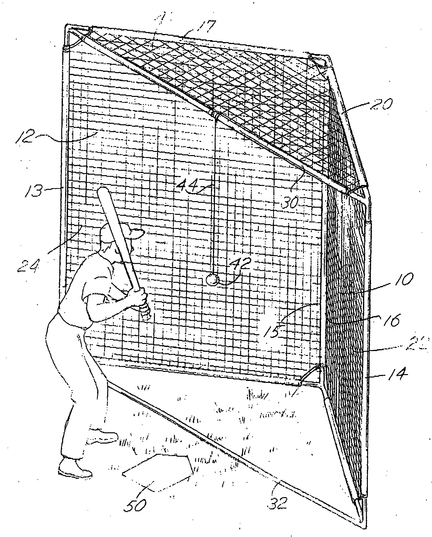
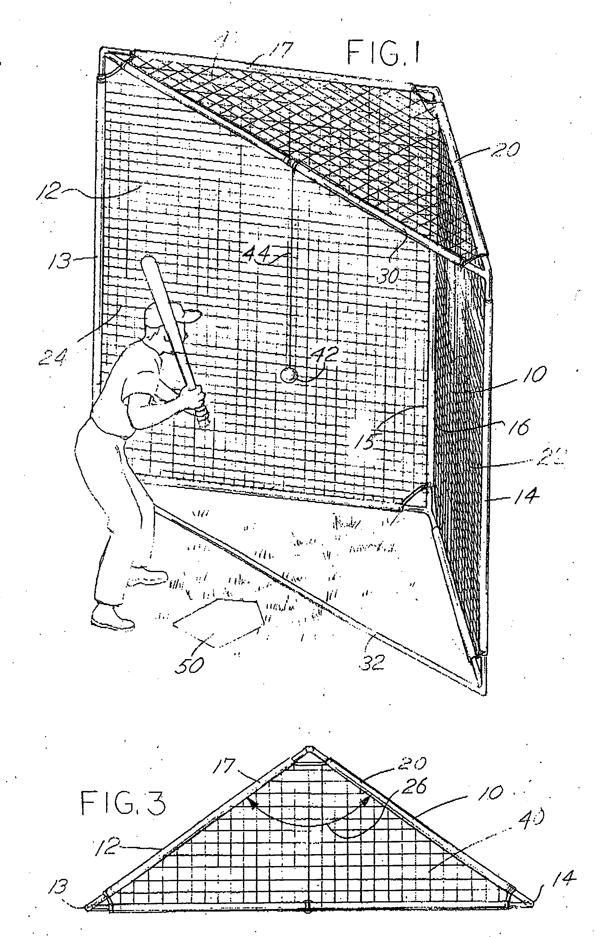
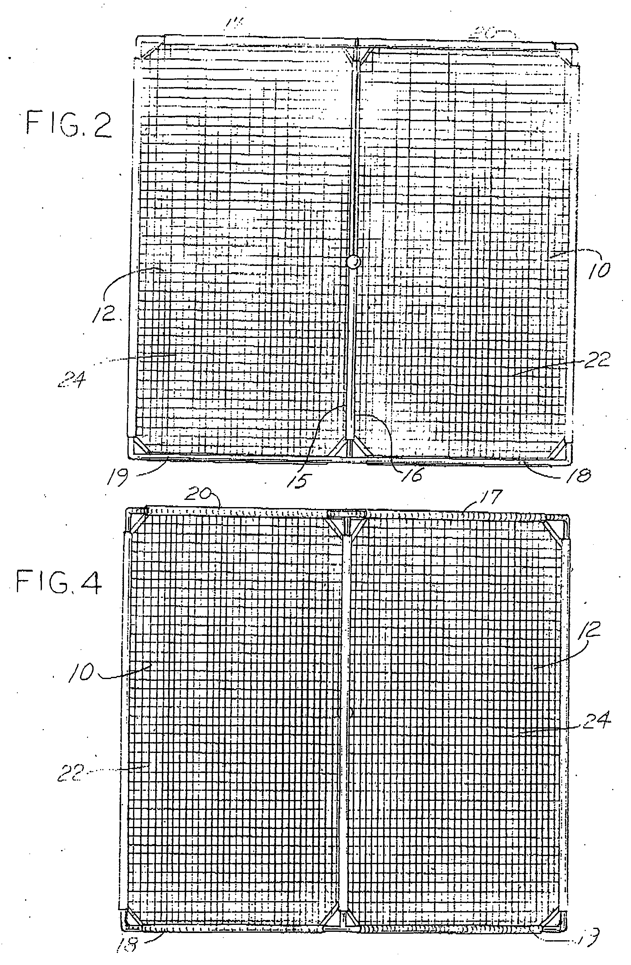
[0020] Referring to the figures, a typical batting or ball striking cage or construction employing features of the invention is comprised of a first generally vertical panel 10 and a second generally vertical panel 12. The panels 10 and 12 are each comprised of a generally rectangular frame including a first lateral side 14 and a spaced, second lateral side 16, a bottom side 18, and a top side 20 for the panel 10. Similarly, the panel 12 includes a first lateral side 13, a second lateral side 15, a top side 17 and a bottom side 19. The described combinations of four sides are joined together to form generally rectangular panels and each panel 10 or 12 includes a netting material 22 and 24, respectively, filling the region in the frames 10 and 12 defined by the sides. The netting material 22, 24 is generally elastic and the choice of the material may be varied in order to change the elastic characteristics of the panels 10 and 12. Examples of netting material include type 728 nylon h...


PUM


Abstract

A batting cage device comprises vertically arranged first and second panels forming an included angle with a ball tethered between the panels to enable a hitter to hit the ball into one of the panels from which it will rebound with various spins and other characteristics to improve the skill of the batter or hitter.

Description

CROSS REFERENCE TO RELATED APPLICATION [0001] This is a utility application based, in part, upon previously filed provisional application Ser. No. 60 / 694,729 filed Jun. 28, 2005 entitled “Batting Cage” which is incorporated herewith by reference and for which priority is claimed. BACKGROUND OF THE INVENTION [0002] In a principal aspect the present invention relates to a batting cage for improving skills in involving the striking of a ball, particularly a baseball, a tennis ball and the like. [0003] Baseball, softball, tennis and other sports typically involve striking a ball with a bat, a racquet or the like. Such sports also require multiple participants, such as a pitcher, catcher, etc., or an opponent. Thus, practice of the skills required in order to participate in such sports may well be limited unless a device or apparatus is made available which will enable an individual to hone their skills. In this regard, numerous patents and products have been developed which involve stri...

Claims


Application Information

Patent Timeline
IPC IPC(8): A63B67/00A63B69/00
CPCA63B69/0079A63B2069/0008A63B71/022
Inventor MOONEY, BERT EDWARD
Owner MOONEY BERT E
Why Eureka
Try Eureka