Connecting system for connecting the parts of a garment display device, and garment display device comprising the connecting system

a technology of connecting system and display device, which is applied in the direction of garments, furniture joining, application, etc., can solve the problems of insufficient retention of rods or pins, cracking or breaking of rim portions, and affecting so as to achieve the effect of substantially improving the stability of display devi

Inactive Publication Date: 2007-01-04
MANIQUIES SEMPERE
View PDF5 Cites 1 Cited by
  • Summary
  • Abstract
  • Description
  • Claims
  • Application Information

AI Technical Summary

Benefits of technology

[0006] It is a first and principal object of the present invention to solve the aforementioned problem of conventional systems for connecting the at least two parts which garment display devices are comprised of, by providing a fastening means that allows to avoid the use of pins or rods that pierce into the material of the wall portions of any of said two parts, and to additionally solve the aforementioned problem of non-uniform distance between the at least two parts which garment display devices are comprised of.
[0031] As apparent from the above, the present invention allows securing the hollow parts of a garment display device to each other avoiding the problems of cracks or breakage that occur in garment display devices comprising conventional connecting means.
[0032] In the above mentioned second preferred embodiment, the bottom surfaces of the hollow parts of the garment display device are totally flat. As the hollow parts are firmly connected to each other at predetermined positions, also the bottom surfaces of the hollow parts are rigidly connected to each other and no relative movement between the parts may occur. Also, in view of the fact that the hollow parts the display device is comprised of are securely fastened to each other, deformation of the material of the hollow does not result in a deformation of the bottom portion thereof, because the uniform separation of the hollow parts of the display device allows to compensate deformation of said material. This allows the entire bottom surface of the garment display device to be flat so that standing stability of the display device is substantially improved when compared to conventional garment display devices.

Problems solved by technology

Insertion of such thin metal rods or pins may result in the rim portions cracking or breaking as the rods or pins act like nails which for being able to penetrate into the rims and walls must displace wall material causing the adjacent wall material to be compressed.
The cracks or breakage leads to the rods or pins not being sufficiently retained and the two hollow parts of the display device being only deficiently connected to each other.
Thereby, usefulness of conventional garment display devices becomes reduced.
Due to the fact that the two hollow parts of the display device are normally made of inexpensive plastic material which may deform rather easily, and also due to the said parts are often manufactured with rather large dimensional tolerances, gaps at points where the parts should contact each other when the display device is in a assembled state, may form when the plastic material deforms.
This is not achieved by means of the above described conventional connecting means with rods or pins being simply pierced into the rims, as after short use of the device, a lack of the desired uniform separation is very easily produced, such that only some portions of the two parts come to contact each other and other portions become more distanced from each other.
This obviously causes an undesired aesthetic appearance.
It is also noteworthy to take into account that known garment conventional display devices have problems related to stability, since the bottom part thereof is usually not totally flat so that when the display device stands on a horizontal surface it is unstable and may rock or even fall over.

Method used


Image

  • Connecting system for connecting the parts of a garment display device, and garment display device comprising the connecting system
  • Connecting system for connecting the parts of a garment display device, and garment display device comprising the connecting system
  • Connecting system for connecting the parts of a garment display device, and garment display device comprising the connecting system

Examples


first embodiment

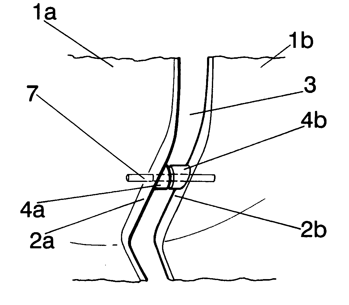
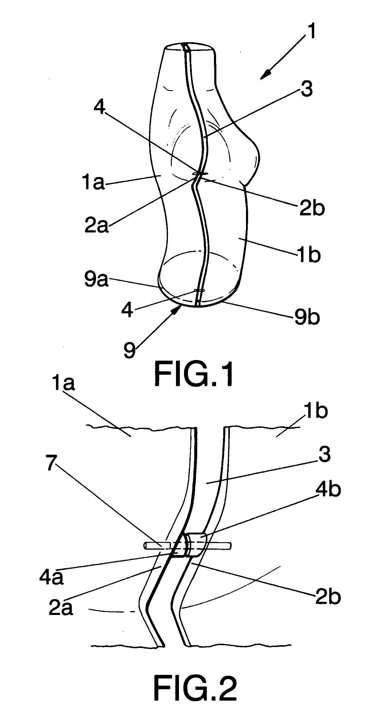
[0035]FIG. 2 is a more detailed view of the connection between the two parts of the torso represented in FIG. 1;

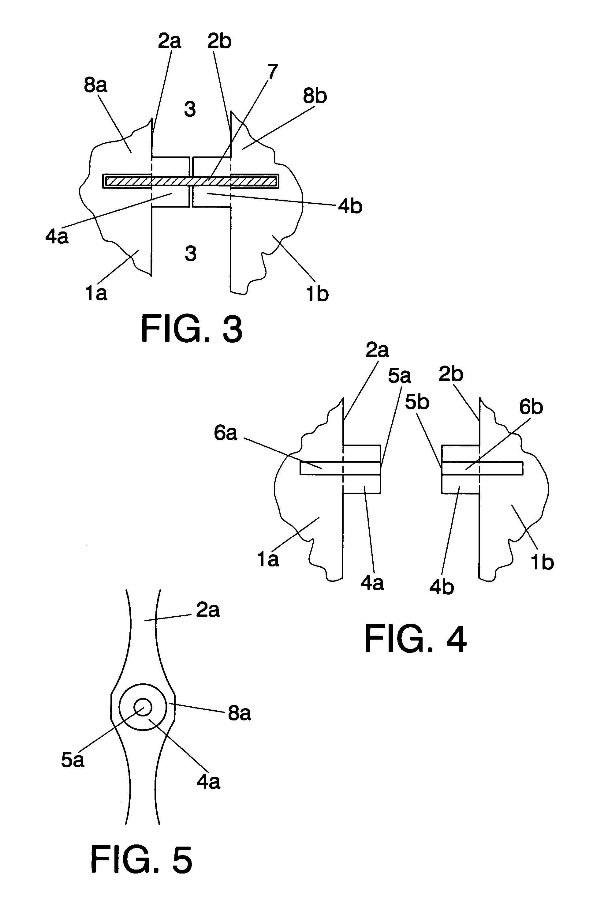
[0036]FIG. 3 is an enlarged front sectional view of the connection shown in FIG. 2;

[0037]FIG. 4 is a front sectional view corresponding to FIG. 3 but in which the hollow parts are unassembled and without the pin element shown in FIG. 3;

[0038]FIG. 5 is a side view from the left of the left rim portion shown in FIG. 4;

second embodiment

[0039]FIG. 6 is a front sectional view of the fastening means of the invention;

[0040]FIG. 7 is a front sectional view corresponding to FIG. 6 but in which the hollow parts are unassembled and without the pin element shown in FIG. 6;

[0041]FIG. 8 is a side view from the left of the left rim portion shown in FIG. 7;

[0042]FIG. 9 is a side view from the right of the right rim portion shown in FIG. 8;

third embodiment

[0043]FIG. 10 is a front sectional view of the fastening means of the invention;

[0044]FIG. 11 is a front sectional view corresponding to FIG. 10 but in which the hollow parts are unassembled and without the pin element shown in FIG. 10;

[0045]FIG. 12 is a side view from the left of the left rim portion shown in FIG. 11

[0046] The reference numerals appearing in these figures denote the following elements

[0047]1 garment display device

[0048]1a first part of the display device

[0049]1b second part of the display device

[0050]2a first perimetric rim portion

[0051]2b second perimetric rim portion

[0052]3 gap

[0053]4 fastening means

[0054]4a first projection

[0055]4b second projection

[0056]5a first opening

[0057]5b second opening

[0058]6a first internal hollow section

[0059]6b second internal hollow section

[0060]7 pin element

[0061]8a first reinforced area

[0062]8b second reinforced area

[0063]9 bottom portion of the display device

[0064]9a bottom portion of first part of the display d...


PUM


Abstract

A connecting system for connecting a first hollow part and a second hollow part of a garment display device being in a shape of at least a portion of a human body, the first part and the second part comprising perimetric rim portions facing each other when the display device is in an assembled state, with fastening means comprising a projection protruding from each of the rim portion which comprises an opening extending into an internal hollow section, the projections being positioned such that said openings in each of the projections face each other when the display device is in said assembled state; a pin element fitting within the hollow sections for connecting the projections to each other.

Description

TECHNICAL FIELD OF THE INVENTION [0001] The present invention pertains to the technical field of garment display devices that are in the shape of at least a portion of a human body such as busts, torsos, legs or arms, or entire human bodies, and more particularly in the sector of garment display devices comprising two hollow parts that are connected to each other by a connecting system. BACKGROUND OF THE INVENTION [0002] Many garment display devices for articles of clothing in the shape of at least a portion of a human body are normally comprised of two rigid hollow plastic parts or halves that are connected to each other by fastening means. [0003] Said two parts are obtained by molding or injection. Each of said two parts comprises a perimetric rim. The parts are connected to each other at said rims by means of thin transversal metal rods or pins that are pierced through the rims into the walls of two parts or halves to be connected to each other. Insertion of such thin metal rods ...

Claims


Application Information

Patent Timeline
Patent Type & Authority Applications(United States)
IPC IPC(8): A41F1/00
CPCA47F8/00F16B12/24Y10T24/45037
Inventor JUAN DE DIOS, SEMPERE LEAL
Owner MANIQUIES SEMPERE
Why Eureka
Try Eureka