Coiled tubing dimple connection

Inactive Publication Date: 2007-01-04
SCHLUMBERGER TECH CORP
View PDF21 Cites 25 Cited by
  • Summary
  • Abstract
  • Description
  • Claims
  • Application Information

AI Technical Summary

Benefits of technology

[0010] In view of the foregoing and other considerations, the present invention relat

Problems solved by technology

It also occurs when the amount of coiled tubing required to perform the service cannot be contained on a single reel as one continuous length of pipe.
This bending and straightening sequence causes low cycle fatigue in the coiled tubing and the connector.
Problems that occur when using dimples to connect coiled tubing to a connector include, but are not limited to, evaluating tensile strength of the connection and providing a solid connection that does not restrict bending of the coil around the reel or gooseneck when two sections of coiled tubing are connected together.
This validates the integrity of the connector for the applied load, but material often yields and could compromise the connection.
When two sections of c

Method used


Image

  • Coiled tubing dimple connection
  • Coiled tubing dimple connection
  • Coiled tubing dimple connection

Examples


Embodiment Construction

[0024] Refer now to the drawings wherein depicted elements are not necessarily shown to scale and wherein like or similar elements are designated by the same reference numeral through the several views.

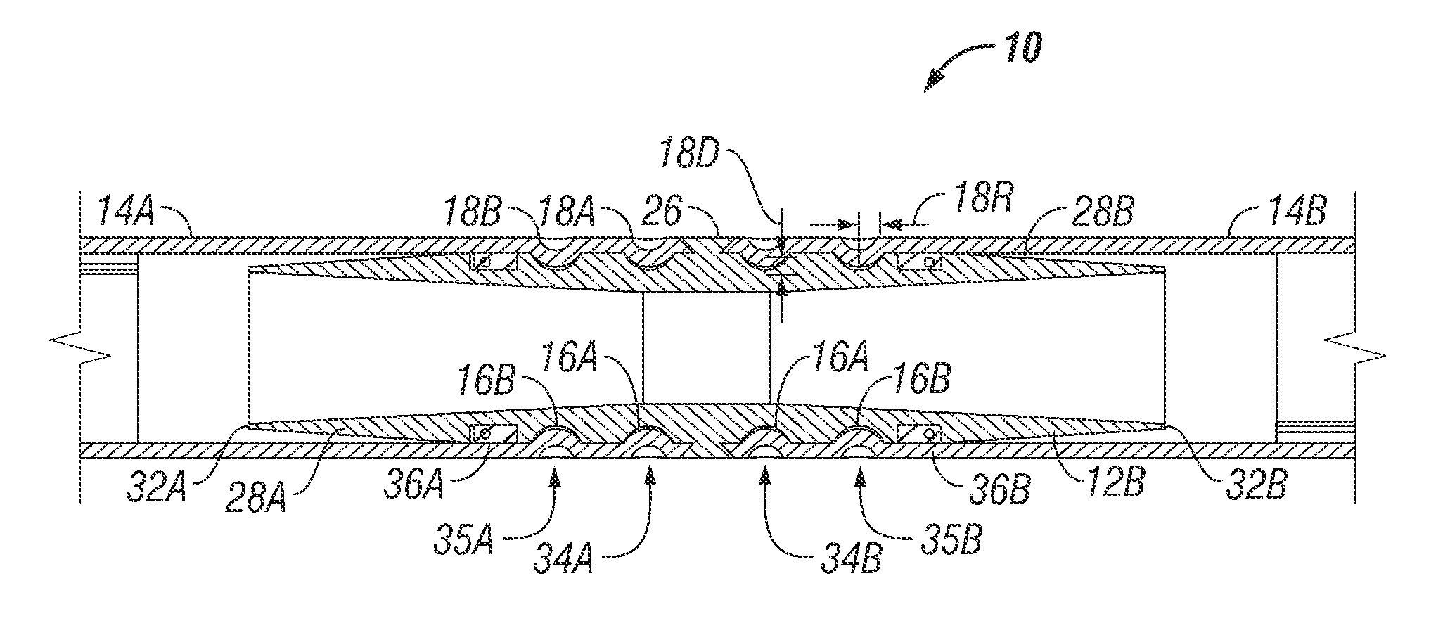
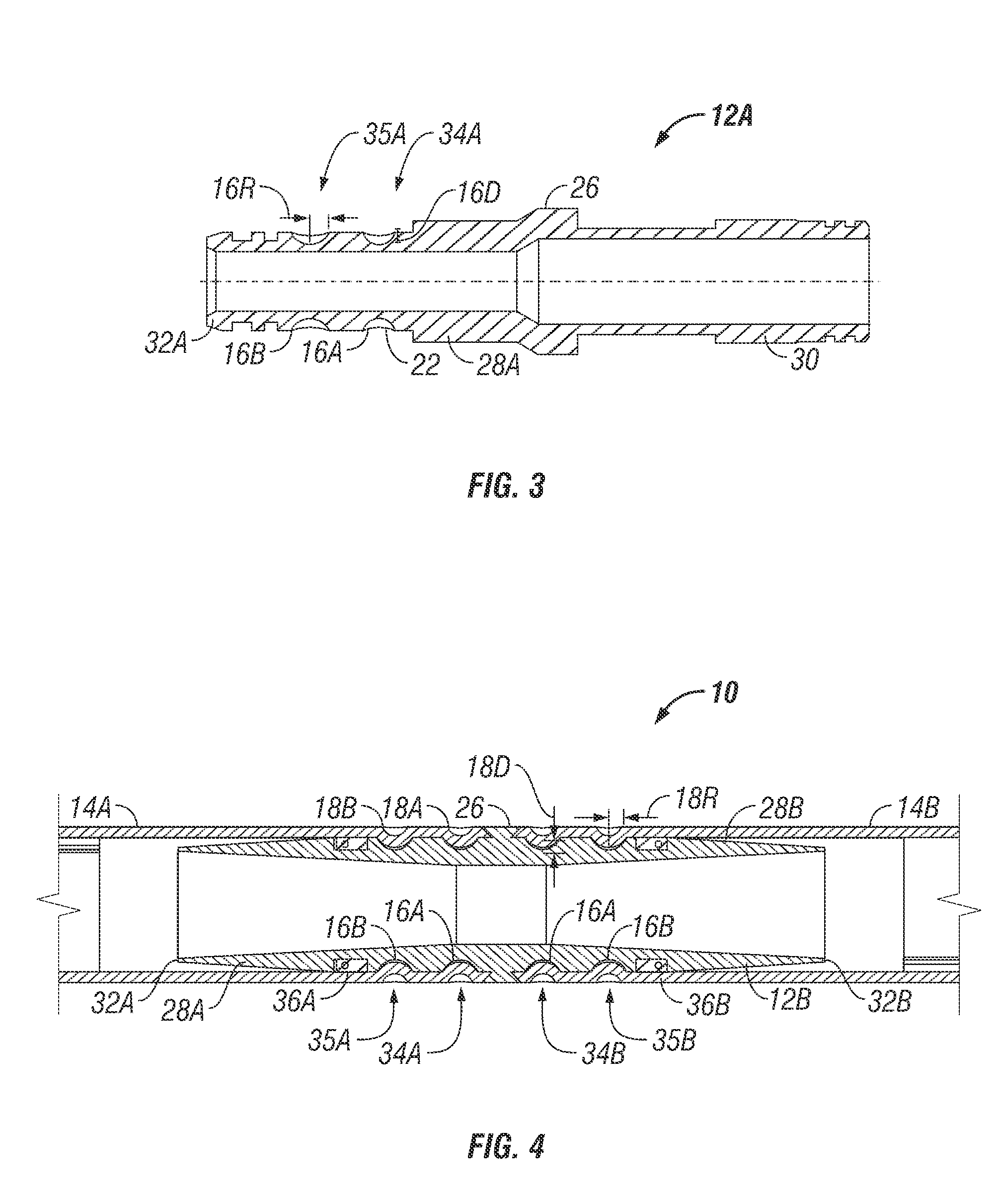
[0025] The present invention provides graduated fit dimple connections between connectors and coiled tubing and methods for validating the strength of a connection while allowing flexibility in the connection to enhance low cycle fatigue performance during bending. A secondary barrier without compromising the performance of the primary seal is also disclosed.

[0026] In general terms, the present invention ensures a secure connection by measuring the depth of the dimples formed in coiled tubing when connecting a connector and a section of coiled tubing together. Further, by controlling the depth of the dimple in the coiled tubing and the diameter and depth of the preformed pockets in the connector, the fit between the coiled tubing and connector can be controlled and graduated. The pr...


PUM

PropertyMeasurementUnit
Lengthaaaaaaaaaa

Abstract

A connection between coiled tubing and a connector includes a plurality of dimples formed by a tubing, each dimple is disposed within a respective pocket formed in a connector to form at least two rows of dimple-pocket connections, wherein the fit of the dimples within the pockets of the rows graduates from tighter to looser along the length of the connection. The connection may further include a seal member positioned between the tubing and the connector positioned between at least two of the rows of dimple-pocket connections formed. A method of connecting coiled tubing to a connector includes the steps of graduating the dimple-pocket connections from tighter to looser along the length of the connection.

Description

[0001] This application claims the benefit of U.S. Provisional Patent Application No. 60 / 695,584 filed Jun. 30, 2005.FIELD OF THE INVENTION [0002] The present invention relates in general to coiled tubing and more specifically to connecting coiled tubing with a connector. BACKGROUND [0003] It is often necessary to provide a connector with coiled tubing. This need occurs when a downhole tool needs to be attached to the end of a string of coiled tubing. It also occurs when the amount of coiled tubing required to perform the service cannot be contained on a single reel as one continuous length of pipe. This could be a result of lift capacity of handling equipment or the volume capacity of the work reel. Additional examples of oilfield circumstances that require a connector include situations such as repairing a leak or a damaged area in an existing continuous length of coiled tubing or retrieving a length of coiled tubing (such as a velocity string) from a well. [0004] One method of co...

Claims


Application Information

Patent Timeline
IPC IPC(8): E21B17/00
CPCE21B17/02Y10T29/49925Y10T29/49927E21B17/20F16L13/14E21B17/041
Inventor MCKEE, L. MICHAELESPINOSA, FRANK F.EATWELL, WILLIAM D.
Owner SCHLUMBERGER TECH CORP
Why Eureka
Try Eureka