Motion-activated soap dispenser

a motion-activated, soap dispenser technology, applied in liquid transfer devices, movable measuring chambers, instruments, etc., can solve the problems of consuming time and requiring at least rudimentary handyman skills, consuming relatively large amounts of power of motion sensors that have been used in automatic dispensers, and existing dispensers

Inactive Publication Date: 2007-01-04
GEKKO TEK
View PDF76 Cites 111 Cited by
  • Summary
  • Abstract
  • Description
  • Claims
  • Application Information

AI Technical Summary

Problems solved by technology

As critically recognized herein, however, existing dispensers typically must be installed in or on a sink surface, consuming time and requiring at least rudimentary handyman skills.
As critically understood herein, however, motion sensors that have been used in automatic dispensers consume relatively large amounts of power, on the order of hundreds of micro amps on average, which can rapidly drain batteries and thus require larger batteries or frequent battery replacement should battery power be used.

Method used


Image

  • Motion-activated soap dispenser
  • Motion-activated soap dispenser
  • Motion-activated soap dispenser

Examples


Embodiment Construction

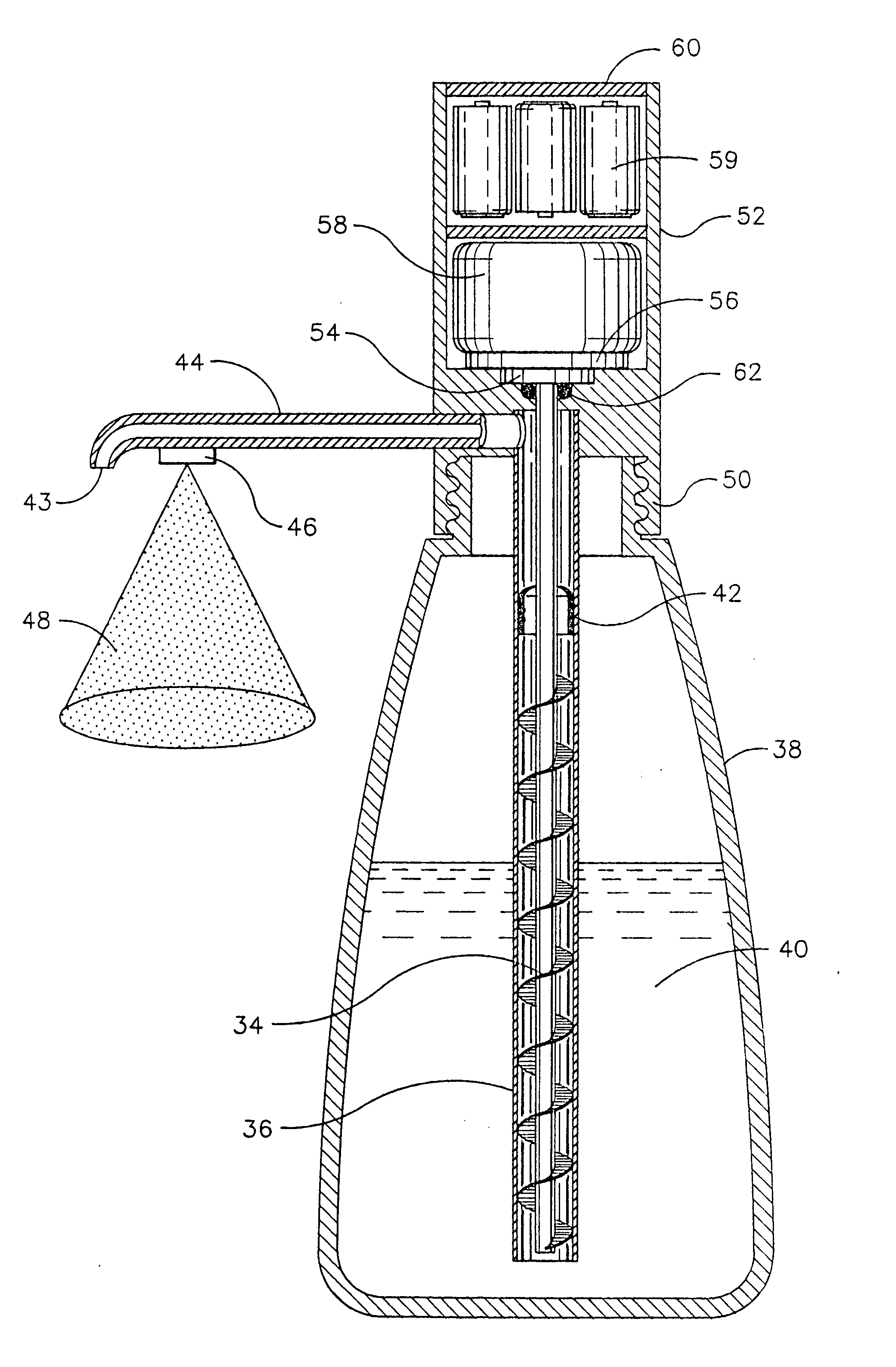
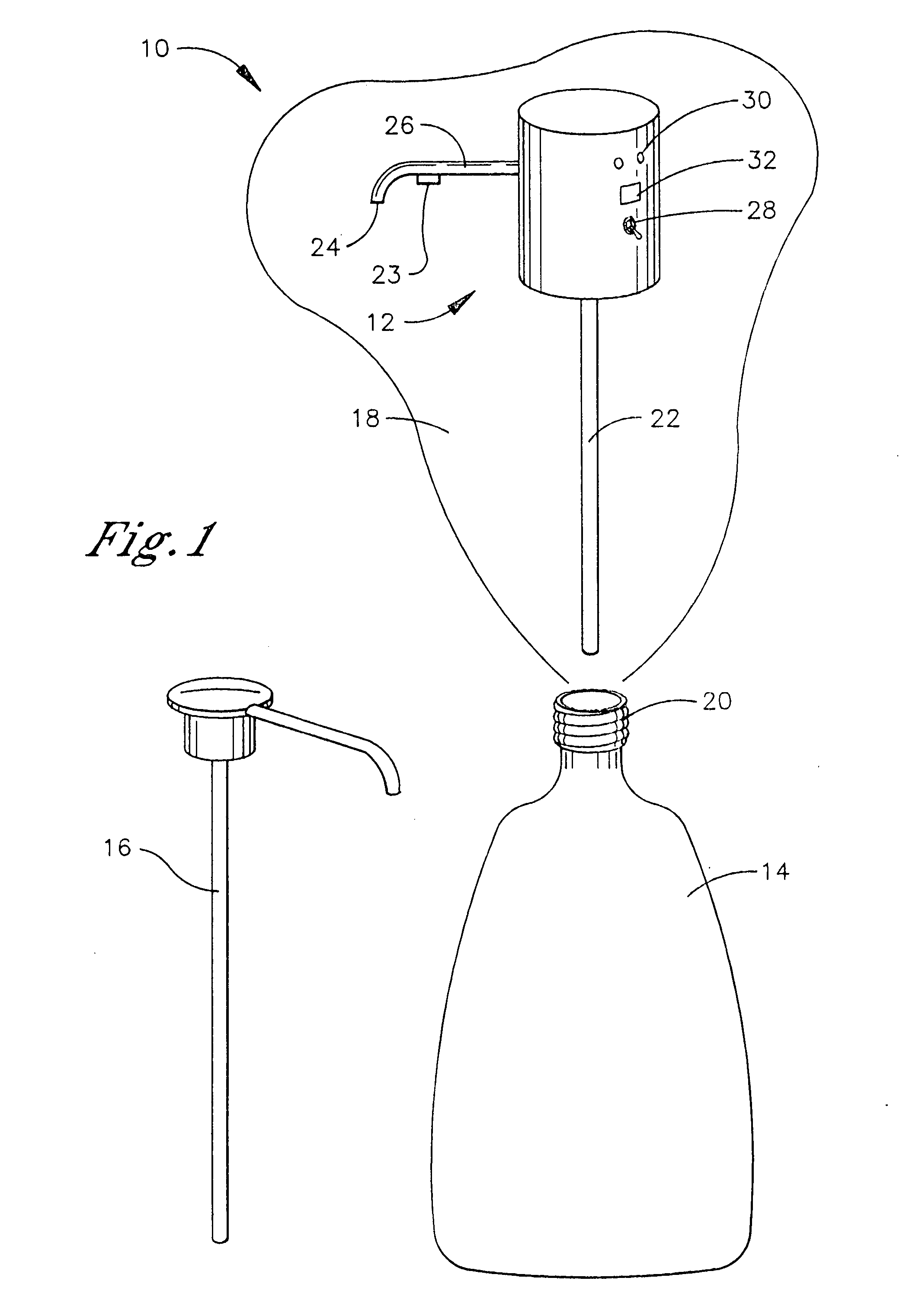
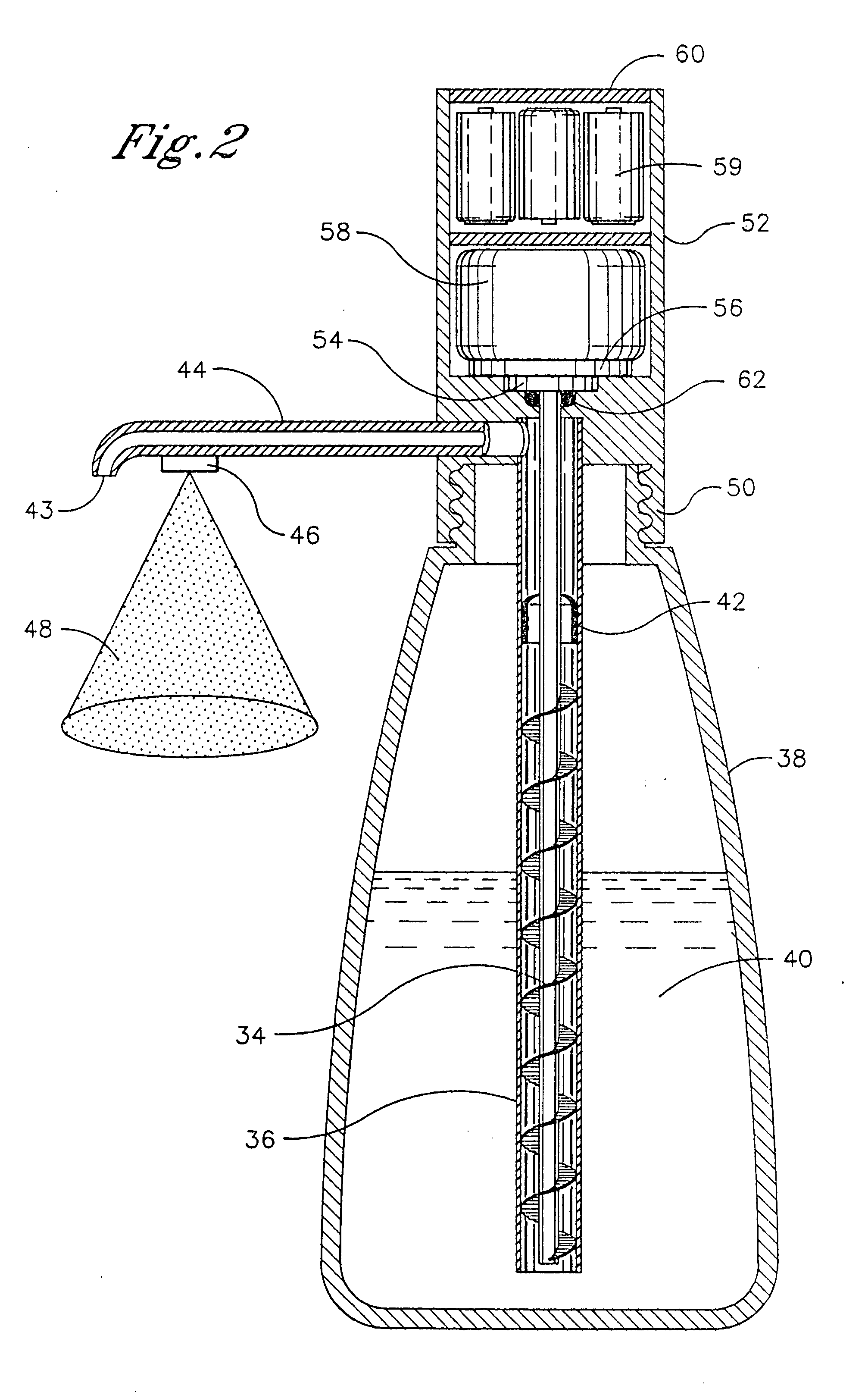
[0020] Referring initially to FIG. 1, a system is shown, generally designated 10, which includes a hollow metal or plastic housing 12 that is configured for threadably engaging a substance container, such as a liquid soap container 14, or a toothpaste container, or a mouthwash container, or hand cream container, or other flowable hygienic substance container. The container 14 for which the housing 12 is configured is a container that is originally associated with a manual pump mechanism 16 as shown for expelling substance such as soap therefrom. Since the housing 12 in one aspect is intended to engage the pre-existing container 14, the housing 12 can be provided in a kit 18 that need not include a container or the substance to be expelled from the container.

[0021] In the embodiment shown the housing 12 is cylindrical and as further disclosed below is configured to threadably engage threads 20 on the container 14. The housing 12 may take other shapes, e.g., it may be parallel-piped-...


PUM


Abstract

A cap member that can be threadably engaged with a conventional soap bottle contains a battery-powered PIR motion detector and a motor responsive to the detector to dispense soap when a hand is sensed nearby.

Description

FIELD OF THE INVENTION [0001] The present invention relates generally to motion-activated household liquid dispensers such as soap dispensers and toothpaste dispensers. BACKGROUND OF THE INVENTION [0002] Soap dispensers that have motion detectors for sensing a nearby hand and emitting a stream of liquid soap in response are known. As critically recognized herein, however, existing dispensers typically must be installed in or on a sink surface, consuming time and requiring at least rudimentary handyman skills. Further, existing dispensers ordinarily are sold with their own specially configured soap containers. The present invention critically recognizes the desirability of retrofitting existing manual pump-type dispensers with motion-sensing automatic dispenser units, an application for which, for the above reasons, existing dispensers are inappropriate or inadequate. [0003] Additionally, for reasons of convenience and ease of installation regardless of retrofitting, the present inve...

Claims


Application Information

Patent Timeline
Patent Type & Authority Applications(United States)
IPC IPC(8): B67D5/08G01F11/20B67D7/08
CPCA47K5/1217
Inventor HADDEN, DAVID M.GABRIEL, GREGORY B.BLUMENKRANZ, STEPHEN J.
Owner GEKKO TEK
Why Eureka
Try Eureka