Multi-positional track lighting device

a lighting device and multi-position technology, applied in the field of lighting systems, can solve the problems of increasing increasing the design complexity, and increasing the cost of the system, so as to increase the complexity of the system, the design is more cumbersome and more costly

Inactive Publication Date: 2007-01-04
PRYOR JAE WON KIM
View PDF9 Cites 19 Cited by
  • Summary
  • Abstract
  • Description
  • Claims
  • Application Information

AI Technical Summary

Benefits of technology

[0005] This design has many benefits. First, because a low voltage electrical current runs through the tracks themselves, there is no need for additional wiring or unnecessary wires, which could make this design more cumbersome and more costly. For example, if the lights had to be electrically connected via additional wiring to the second set of tracks, this would dramatically increase the complexity of the set up of a system. Instead, with the current system, a user only has to add a light using an existing light housing, which receives electrical power directly from the second set of tracks. Thus, a user does not have to electrically connect wires to the first set of tracks or to the second set of tracks to have a light in electrical communication with the system. A user only has to couple a light housing onto the second set of tracks for an additional light to work.
[0006] Since this system does not require unnecessary wires to connect between the first set of tracks and the second set of tracks and also between the second set of tracks and the light or the light housing, this allows for a freer mechanical movement of each of these parts with respect to each other.

Problems solved by technology

First, because a low voltage electrical current runs through the tracks themselves, there is no need for additional wiring or unnecessary wires, which could make this design more cumbersome and more costly.
For example, if the lights had to be electrically connected via additional wiring to the second set of tracks, this would dramatically increase the complexity of the set up of a system.

Method used


Image

  • Multi-positional track lighting device
  • Multi-positional track lighting device
  • Multi-positional track lighting device

Examples


first embodiment

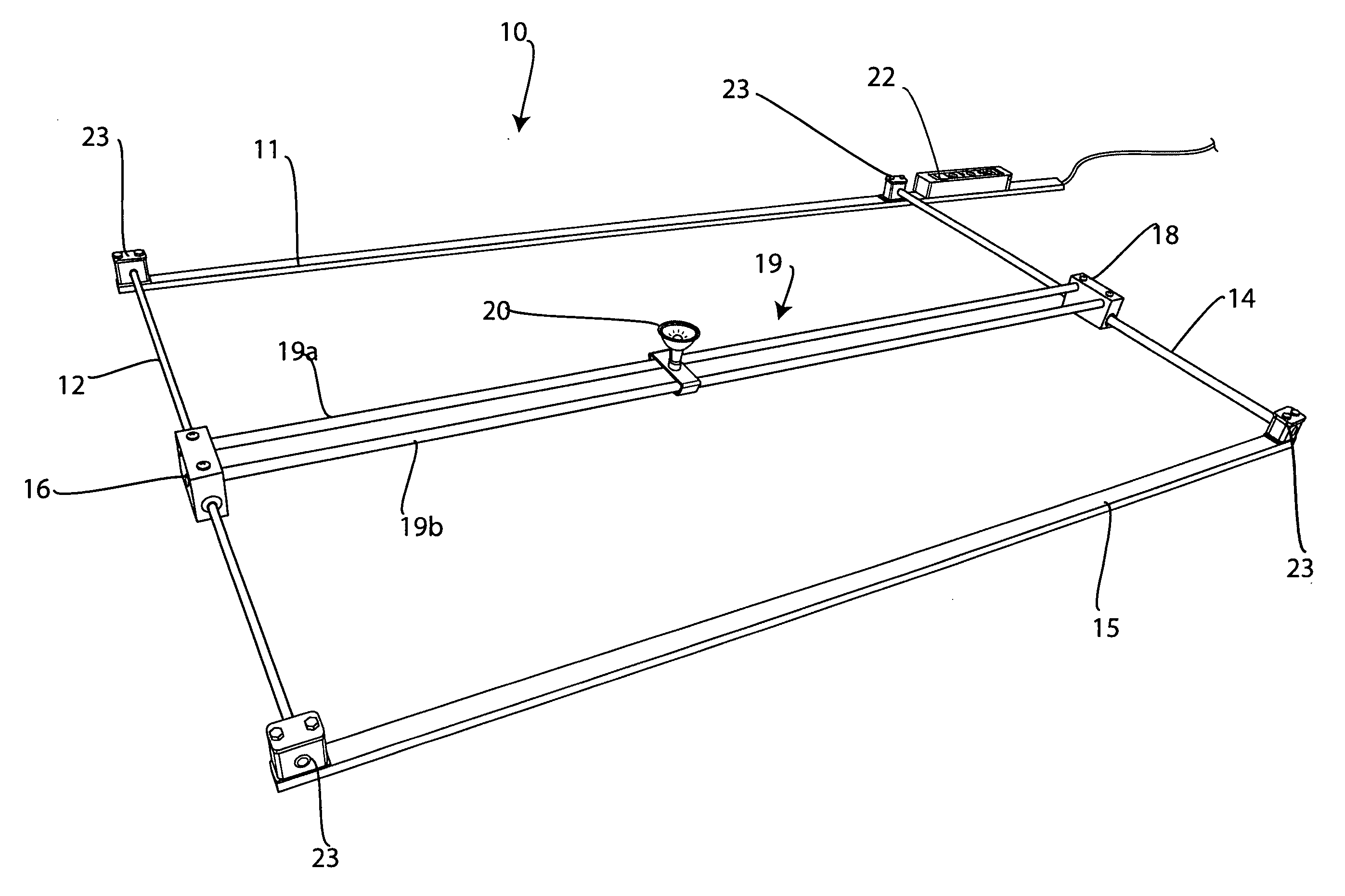
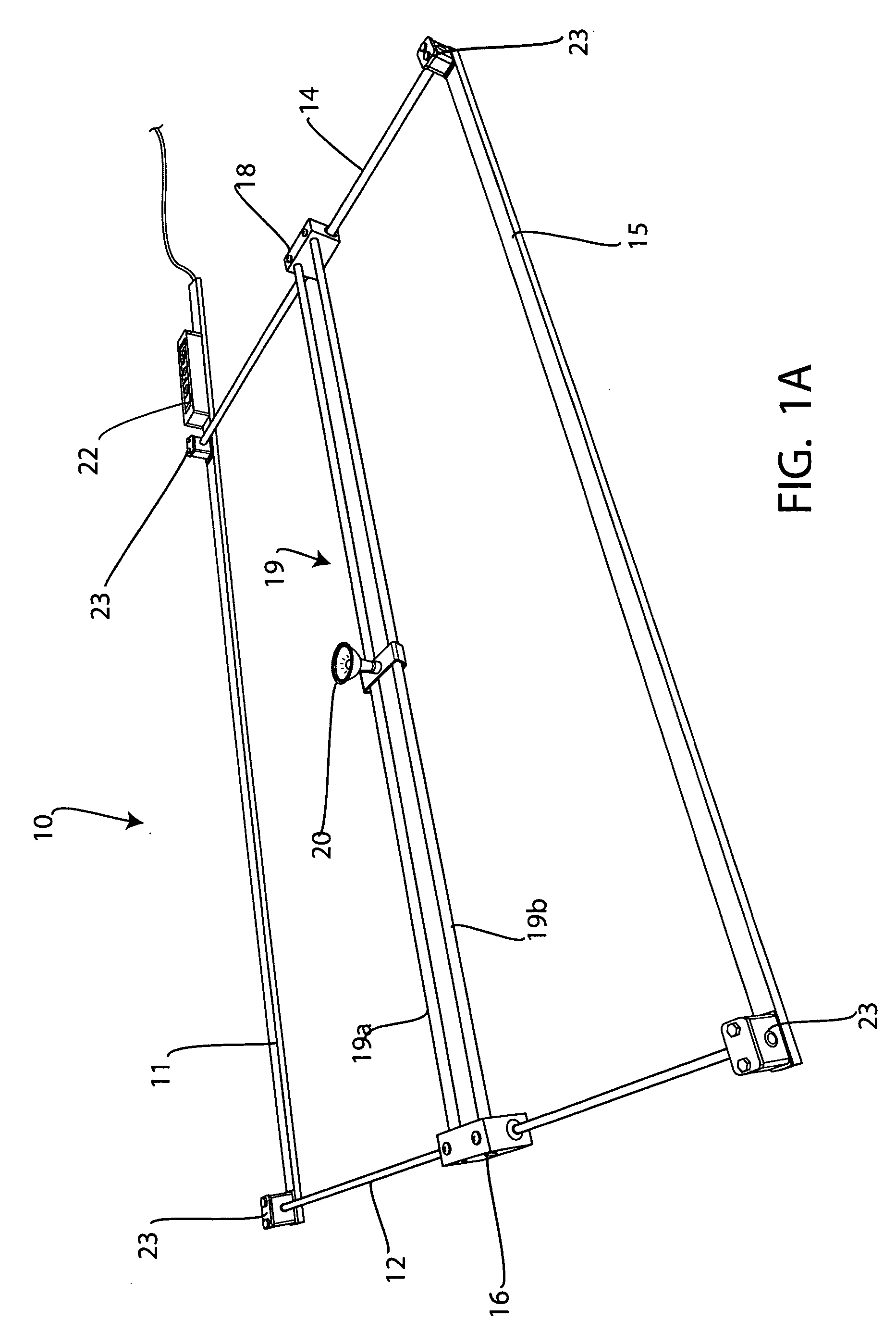
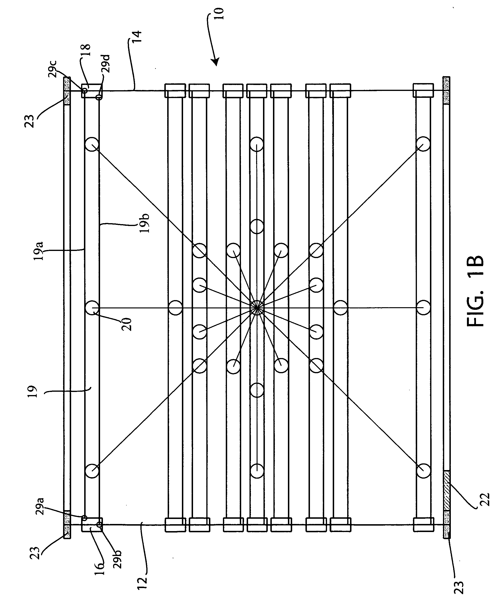
[0057] Referring to the drawings, FIG. 1A shows a perspective view of the device 10 positioned on a floor, and FIG. 1B shows a top view of this invention. This device can be coupled to a floor, wall or ceiling of a building and for example may be coupled to the ceiling of a room at least one light pointing down to the floor.

[0058] The device 10 can include a plurality of tracks or rails 12 and 14 which can be charged with opposite polarity from a power source which may include a transformer 22. This power is bridged via a connection of a plurality of tracks 19 which can include at least two tracks 19a and 19b which allow at least one light 20 to be moved or slid on these tracks 19a and 19b. In addition, tracks 19a and 19b are coupled both mechanically and electrically to tracks 12 and 14 via connection elements 16 and 18. In this way, a track 19 can be slid on parallel extending tracks 12 and 14 to a particular position. In addition, light 20 can be slid or moved or slid on tracks 1...

embodiment 57

[0078] For example, FIG. 6A discloses a coupling element embodiment 57, which can include a first split section 58a and a second split section 58b of a body 58. Body 58 can be made from any known material such as a conductive material which can be aluminum. These split sections (See also FIG. 6B) can be opened to receive any one of the first set of tracks and then screwed closed via screws 60a and 60b to clamp the split sections 58a and 58b closed. This clamping, if done sufficiently tight, can be used to fix this coupling element in place on the associated track 12 or 14 extending through it. In addition, as shown in FIG. 6B, there is also another set screw 62, which can be used to lock directly into a track 12 or 14 to form a selective direct locking connection with track 12 or 14.

[0079] This additional screw 62 can be used to secure a split section 58c to main body 58. As shown in FIG. 6C, which is a side cross-sectional view, there are holes or passageways 53a and 53b, which can...


PUM


Abstract

A lighting system that can be a track lighting system that allows lights to move in different directions such as in both a “x” direction and in a “y” direction. This lighting system can include a set of parallel tracks wherein at least one track is also slidable on this set of parallel spaced tracks. On that track is at least one light that can be electrically and mechanically coupled to that track. The device relies on a low voltage system which allows current to flow through the tracks.

Description

CROSS REFERENCE TO RELATED APPLICATIONS [0001] This application is a non provisional application and hereby claims priority from U.S. Provisional Application Ser. No. 60 / 632,593 filed on Dec. 2, 2004 and Ser. No. 60 / 691,226 filed on Jun. 16, 2005 wherein the disclosures of which are hereby incorporated herein by reference.BACKGROUND OF THE INVENTION [0002] The invention relates to a lighting system that can be a track lighting system that allows lights to move in different directions such as in both a “x” direction and in a “y” direction. Other lighting systems are known. For example, the following U.S. patents generally relate to this field U.S. Pat. No. 6,347,877 to Douglass II; U.S. Pat. No. 3,936,671 to Bobrick et al.; U.S. Pat. No. 5,993,030 to Barcel; U.S. Pat. No. 4,109,305 to Claussen et al.; U.S. Pat. No. 4,591,764 to Nilssen; U.S. Pat. No. 2,905,806 to Tunney; U.S. Pat. No. 5,440,469 to Gomes; U.S. Pat. No. 5,672,003 to Shemitz et al.; U.S. Pat. No. 6,540,372 to Joseph; U....

Claims


Application Information

Patent Timeline
Patent Type & Authority Applications(United States)
IPC IPC(8): F21S8/00
CPCH01R25/147F21V21/35
Inventor PRYOR, JAE WON KIM
Owner PRYOR JAE WON KIM
Why Eureka
Try Eureka