Seal for a cannula

Inactive Publication Date: 2007-01-04
ATROPOS LTD
View PDF99 Cites 143 Cited by
  • Summary
  • Abstract
  • Description
  • Claims
  • Application Information

AI Technical Summary

Benefits of technology

[0010] the first seal being movably coupled to the proximal portion to facilitate relative movement between the first seal and the proximal portion to a

Problems solved by technology

However there are a number of problems associated with such a conventional cannula.
In particular the conventional cannula suffers fr

Method used


Image

  • Seal for a cannula
  • Seal for a cannula
  • Seal for a cannula

Examples


Embodiment Construction

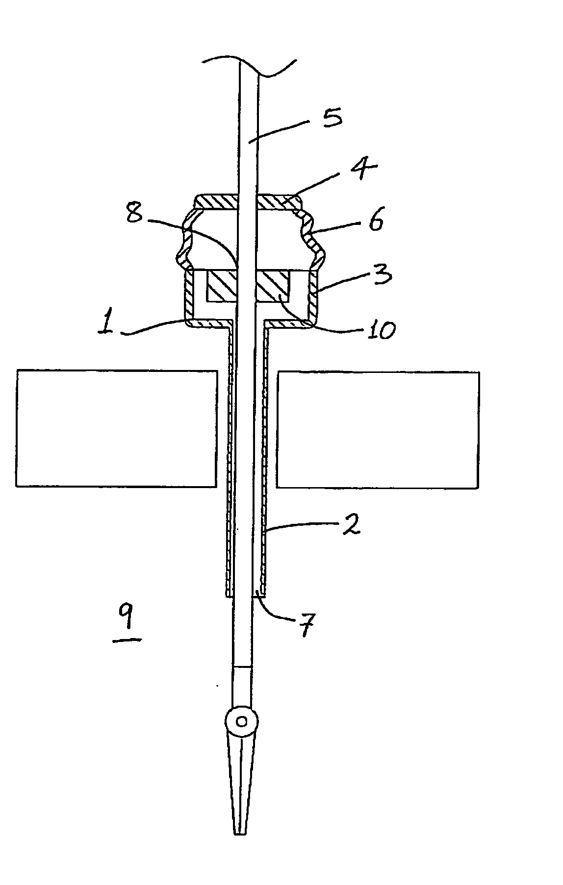
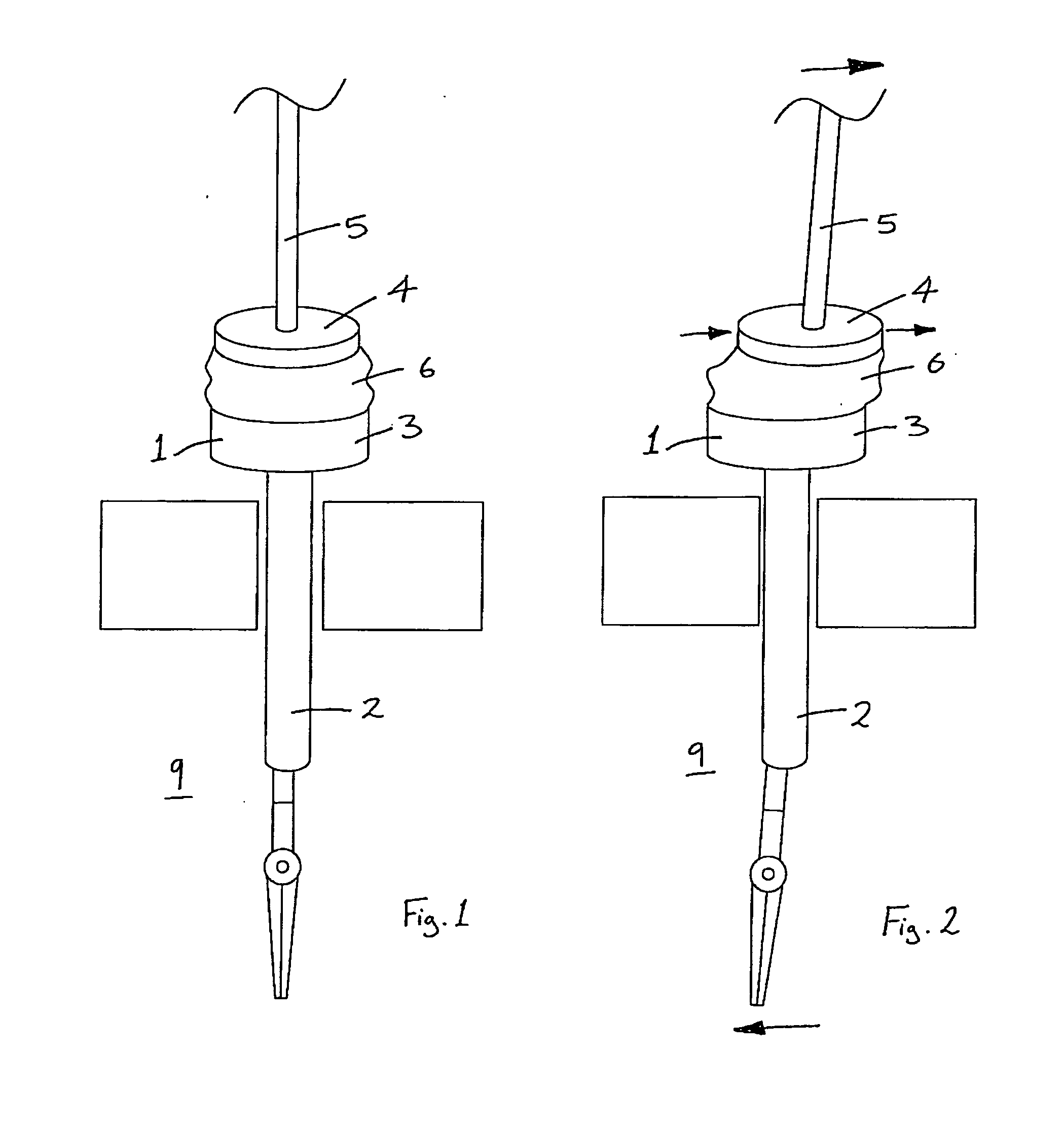
[0028] Referring to the drawings and initially to FIGS. 1 to 4 thereof, there is illustrated a cannula 1 according to the invention.

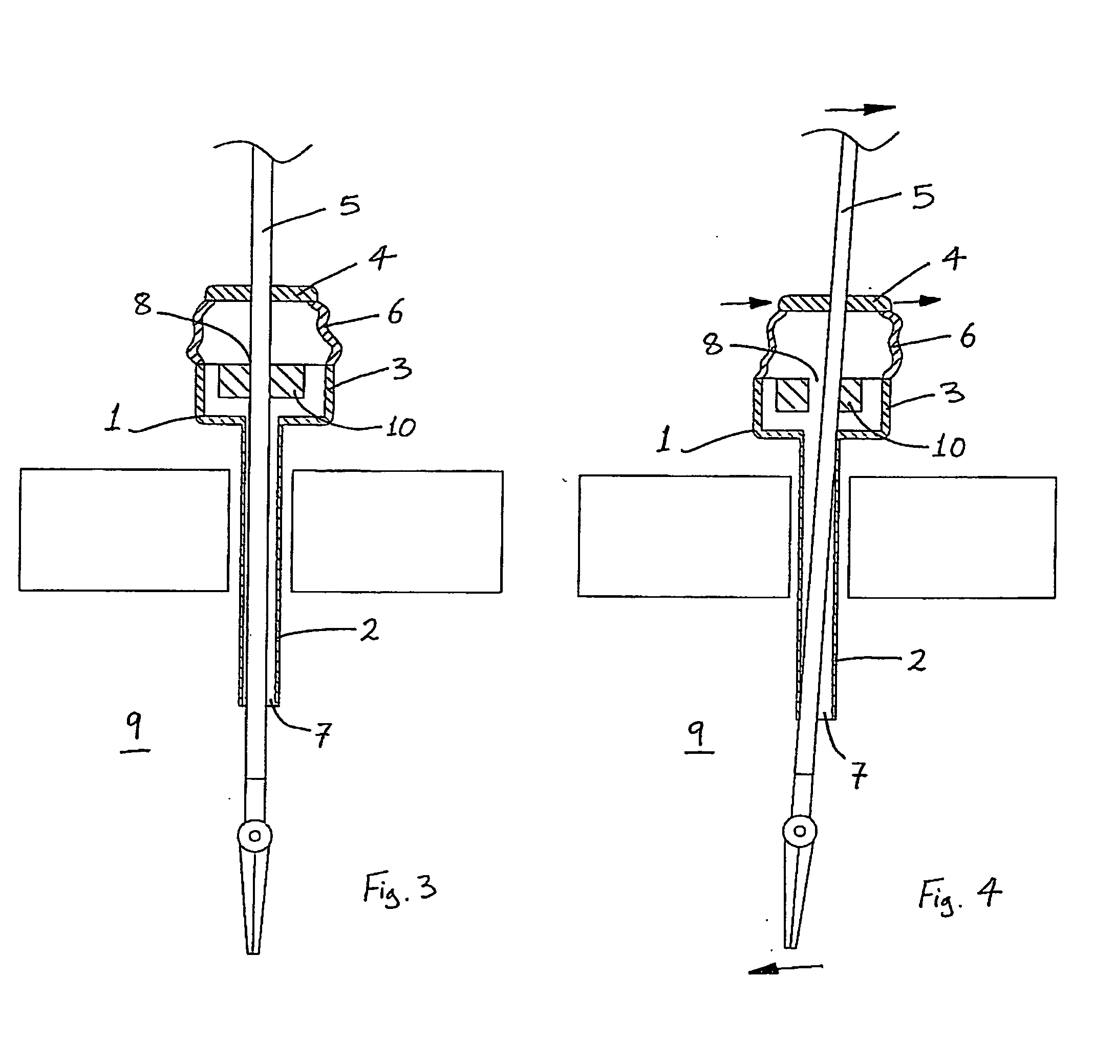
[0029] The cannula 1 comprises a distal hollow tubular section 2, a proximal instrument insertion section 3, a proximal seal in this case a lip seal 4 for sealingly engaging with an instrument shaft 5, and a distal seal in this case a duck-bill seal 10 also for sealingly engaging with the instrument shaft 5. The lip seal 4 is movably coupled to the proximal section 3 by a coupling section, which is provided in this case in the form of a flexible tubular sheath section 6.

[0030] The distal section 2 defines an access channel 7 for extension of the instrument shaft 5 therethrough.

[0031] The proximal section 3 has a proximal opening 8 through which the instrument shaft 5 may be inserted into the proximal section 3.

[0032] The lip seal 4 is located externally of the proximal section 3, proximally of the proximal opening 8.

[0033] The duck-bill seal 10 is ...


PUM


Abstract

A cannula (1) comprises a distal hollow tubular section (2), a proximal instrument insertion section (3), a lip seal (4) for sealingly engaging with an instrument shaft (5), and a duck-bill seal (10) also for sealingly engaging with the instrument shaft (5). The lip seal (4) is movably coupled to the proximal section (3) by a coupling section, provided in the form of a flexible tubular sheath section (6). The distal section (2) defines an access channel (7) for extension of the instrument shaft (5) therethrough. The proximal section (3) has a proximal opening (8) through which the instrument shaft (5) may be inserted into the proximal section (3). The distal end of the flexible section (6) is fixedly attached to the proximal section (3), and the proximal end of the flexible section (6) is fixedly attached to the lip seal (4). The flexible section (6) facilitates relative movement between the lip seal (4) and the proximal section (3) to accommodate lateral movement of the instrument (5) while maintaining the seal between the lip seal (4) and the instrument (5).

Description

[0001] This invention relates to a medical device known as a cannula. [0002] The use of a conventional cannula to gain access as a means to see inside the abdomen or to introduce surgical instruments into the abdomen has existed since the late 19th century. A conventional cannula is a rigid tube, which is inserted through the abdominal wall and is held in place by the tension of the abdominal wall itself around the inserted cannula. [0003] Minimally invasive surgery is an evolving surgical method that attempts to reduce the size of incisions required, in many cases dramatically. By using a conventional cannula, the surgeon can gain access with instruments into the abdominal cavity to carry out an operation through a series of very small holes in the abdominal wall. Unlike in the case of “open surgery”, primary retraction is accomplished by lifting the abdominal wall away from the abdominal viscera. This is most often accomplished with the use of gas in a technique known as insufflat...

Claims


Application Information

Patent Timeline
IPC IPC(8): A61B1/32
CPCA61B17/3462
Inventor BONADIO, FRANKVAUGH, TREVOR
Owner ATROPOS LTD
Why Eureka
Try Eureka