
Intravaginal device with controlled expansion

a controlled expansion and intravaginal technology, applied in the field of intravaginal devices, can solve the problems of affecting the use of tampons

Inactive Publication Date: 2007-01-04
JOHNSON & JOHNSON CONSUMER COPANIES
View PDF99 Cites 8 Cited by
  • Summary
  • Abstract
  • Description
  • Claims
  • Application Information

AI Technical Summary

Benefits of technology

The patent describes a way to make tampons that don't fail prematurely. By attaching a cover to the tampon before or after it is compressed, certain parts of the tampon can expand while other parts are restricted from expanding. This helps to keep the tampon in its original form and prevents it from leaking or getting stuck. The cover can be made from shrinkable materials or binding agents that limit the expansion of the tampon when it absorbs bodily fluid. This technique also allows for the addition of a secondary cover to further restrict the expansion of the tampon. Overall, this method improves the reliability and performance of tampons.

Problems solved by technology

This leads to a substantially uncontrolled expansion of the tampon, depending only on the fluid concentration on and the fluid distribution to the tampon.
A drawback often encountered with commercially available tampons is the tendency toward premature failure, which may be defined as bodily fluid leakage from the vagina while the tampon is in place, and before the tampon is completely saturated with the bodily fluid.
The patent art typically describes a problem believed to occur when an unexpanded, compressed tampon is unable to immediately absorb fluid.
Therefore, it presumes that premature leakage may occur when bodily fluid contacts a portion of the compressed tampon, and the fluid is not readily absorbed.
Unfortunately, the secondary absorbent element may affect comfort of the wearer as it is close to vaginal opening.
While the prior art is replete with examples of sanitary protection articles is that capture bodily fluids intravaginally, these examples do not overcome the problem of premature failure often identified as by-pass leakage that commonly occurs while using internal sanitary protection devices.
Many solutions to this problem have involved adding elements before the tampon pledget is compressed and hence the expansion of the tampon when body fluid contacts it is not controlled.

Method used


Image

  • Intravaginal device with controlled expansion
  • Intravaginal device with controlled expansion
  • Intravaginal device with controlled expansion

Examples


Embodiment Construction

[0026] As used herein in the Specification and the Claims, the term “bodily fluid” and variants thereof mean bodily exudates, especially liquids that are produced by, secreted by, emanate from, and / or discharged from a human body.

[0027] As used herein in the Specification and the Claims, the term “fluids” and variants thereof relate to liquids, and especially bodily fluids.

[0028] As used herein in the Specification and the Claims, the term “in fluid communication” and variants thereof relate to elements that are arranged and configured to allow fluid to move therebetween. The fluid movement may be by interfiber capillary movement, intrafiber capillary movement, osmotic pressure, interplate capillary action, mechanical channeling, and the like.

[0029] As used herein, the term fluid storage element relates to any absorbent medium that forms the absorbent portion of the intravaginal device. In a tampon, the fluid storage element could also be known as the absorbent core. The fluid st...


PUM


Abstract

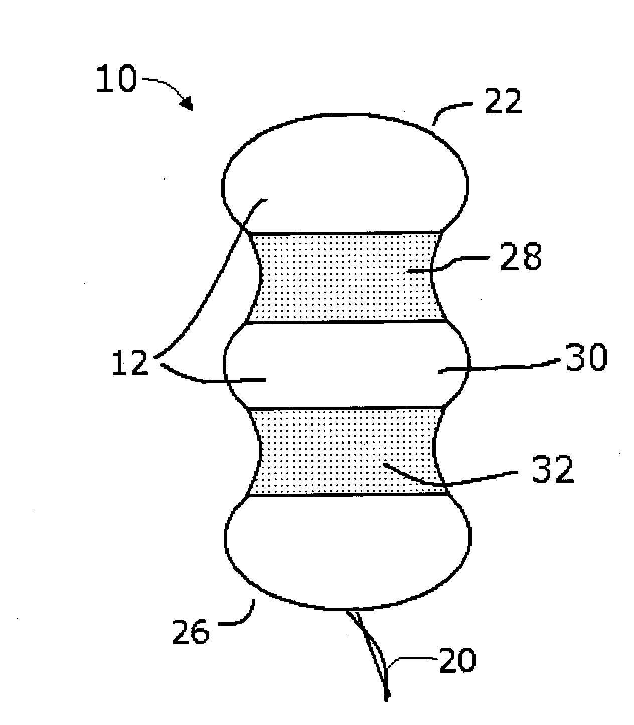
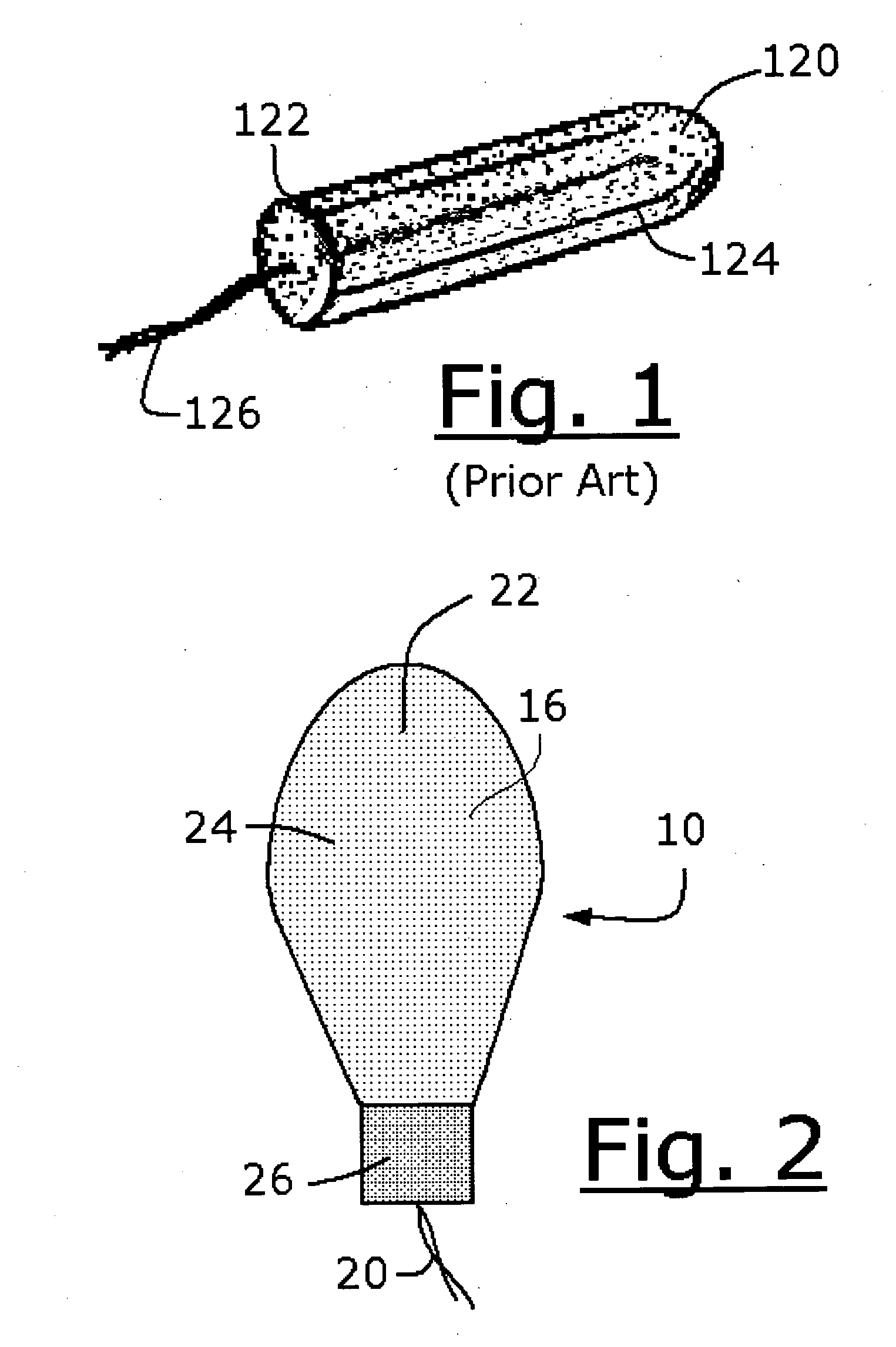
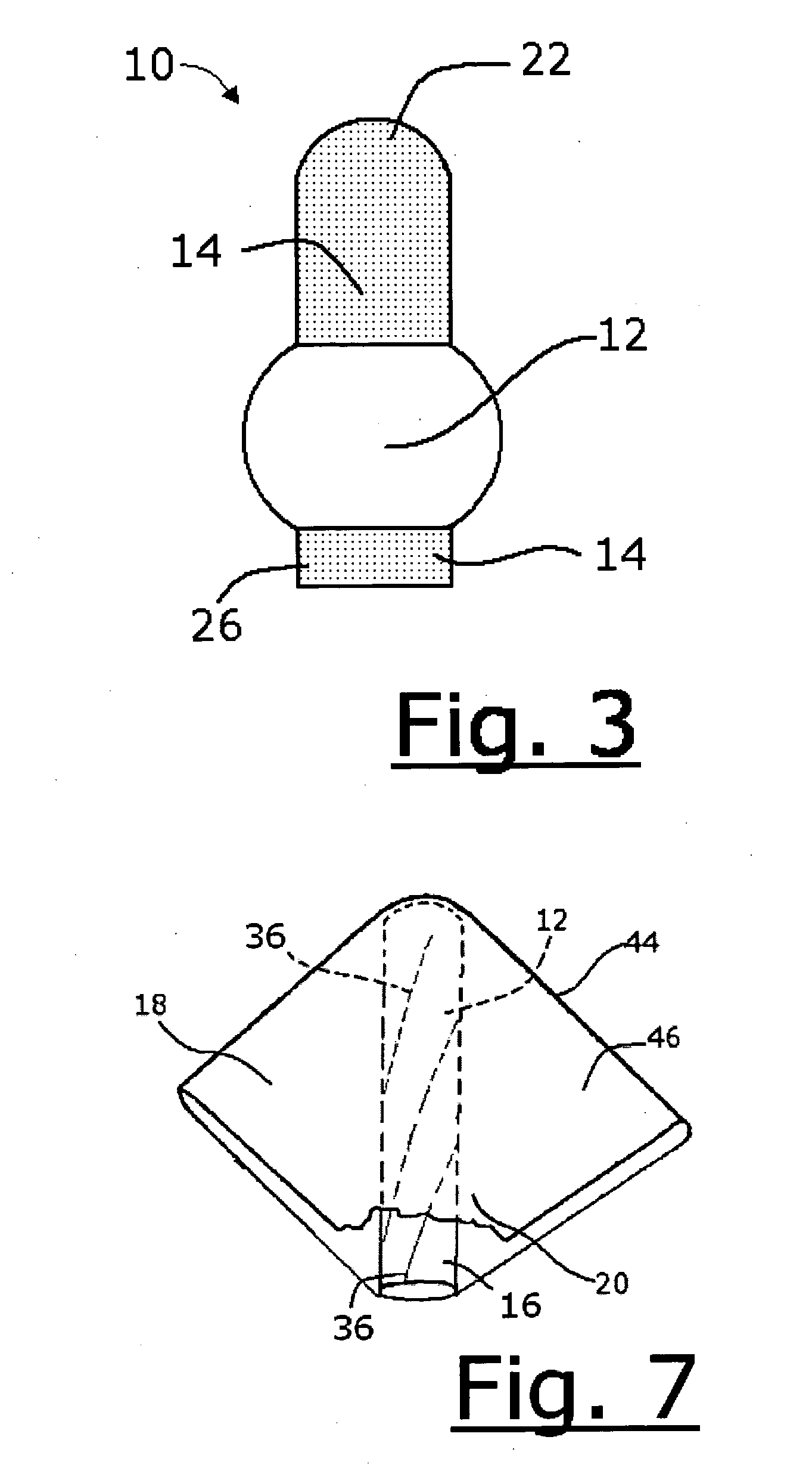
Controlled expansion of an intravaginal device can be achieved by selectively attaching either a primary or secondary cover to the primary absorbent device having a fluid storage element, we can determine that certain portions of the tampon will expand while other portions will be restricted to substantially the compressed structure. The primary cover can be attached to the primary absorbent device either before or after the absorbent device is compressed into final tampon form. The compression may be in the axial or radial direction or a combination of both directions. The secondary cover, if used, can be attached after the tampon pledget has been compressed into the final tampon form.

Description

CROSS-REFERENCE TO RELATED APPLICATIONS [0001] This invention is related to the following copending applications filed on even date herewith: “Intravaginal Device with Fluid Acquisition Plates” (U.S. Ser. No. 60 / 572,054; Atty. Docket No. PPC-5073), “Intravaginal Device with Fluid Acquisition Plates” (U.S. Ser. No. 10 / 847,952; Atty. Docket No. PPC-5070 G-2), “Fluid Management Device with Fluid Transport Element for use within a Body” (U.S. Ser. No. 10 / 847,951; Atty. Docket No. PPC-5071 G-2a), “Method of Using Intravaginal Device with Fluid Transport Plates” (U.S. Ser. No. 10 / 848,208; Atty. Docket No. PPC-5075 G-14a), “Tampon with Flexible Panels” (U.S. Ser. No. 10 / 848,257; Atty Docket No. PPC-5074 G-2b), and “Method of Using an Intravaginal Device with Fluid Transport Plates” (U.S. Ser. No. 10 / 848,347; Atty. Docket No. PPC-5076 G-14), the content of each of which is incorporated herein.FIELD OF THE INVENTION [0002] The present invention relates to devices for capturing and storing bo...

Claims


Application Information

Patent Timeline
Patent Type & Authority Applications(United States)
IPC IPC(8): A61F13/20
CPCA61F13/2051A61F13/2071A61F13/20A61F13/2068A61F13/202A61F13/2022
Inventor BIGGS, JEHANNCARASSO, SAMUELMARSEE, ERINGLASGOW, TARAKOZOROVITSKY, JULIAMARCUS, GINA J.
Owner JOHNSON & JOHNSON CONSUMER COPANIES
Learn More