Electrical cable resistant to fire, water and mechanical stresses

a technology of electrical cables and insulating layers, applied in the direction of cables, insulated conductors, conductors, etc., can solve the problems of excessive intensity, insufficient protection of mechanical stresses by copper strips and glass fibre strips, and softening of the elastomeric insulating layer, so as to hinder the slight expansion of the ceramifying polymer, increase its own volume, and inhibit the propagation of fumes

Active Publication Date: 2016-05-03
PRYSMIAN SPA
View PDF25 Cites 5 Cited by
  • Summary
  • Abstract
  • Description
  • Claims
  • Application Information

AI Technical Summary

Benefits of technology

[0046]If this electrical cable is subjected to fire, the discontinuous layer of inorganic material and the layer of ceramifying polymer of the insulating coating show stable behaviour, i.e. they do not soften and do not collapse. In particular, the ceramifying polymer forms a layer of compact ashes, slightly increasing its own volume. The screen, if present, positioned radially outside the polymer, has a discontinuous structure and therefore does not hinder the slight expansion of the ceramifying polymer, and does not hinder any propagation of fumes along the cable which contributes to preserve the integrity of the whole cable. The structural stability of the whole cable is thus advantageously maintained even in the presence of fire. In particular, the integrity of the barrier is suitably conserved. Because of its three-layered structure and of the nature of these layers, this barrier provides the cable with high impermeability to water and to mechanical stresses, even in the presence of fire.

Problems solved by technology

In particular, in the electrical cable described in EP 1 798 737, the combination of copper strip and glass fibre strip does not provide sufficient protection against mechanical stresses—which can be exceptionally intense—which an electrical cable may be subjected to during rescue operations following a fire.
Furthermore, in the presence of flames, the elastomeric insulating layer softens as a result of the rise in temperature, or even burns.
The softened material or the ashes produced by combustion are collapsible and cannot support the outer layers of the cable, which undergo structural collapse.
The latter are therefore no longer capable of providing impermeability to water and adequate protection against mechanical stresses.
In the presence of flames, therefore, they would give rise to the same problems as those mentioned above.
On the other hand, the outer layers of this cable (the silicone rubber layer and the outer braided jacket made of fiberglass material) do not provide either impermeability to water or adequate protection against mechanical stresses in case of flame.
Regarding the cable described in FR 2 573 910, the outer sheath of polymer resin, optionally charged with refractory inorganic particles, ceramifies in the presence of flames, producing a residue which, although fire resistant, cannot provide adequate protection against direct mechanical stresses, as a result of which it may become water-permeable.
In the presence of flames, therefore, it would give rise to the same problems as those mentioned above.
On the other hand, the outer layers of this cable (glass fibre layer, braided metal armour and outer sheathing of polyethylene or polypropylene material) do not provide impermeability to water in the presence of flames.

Method used


Image

  • Electrical cable resistant to fire, water and mechanical stresses
  • Electrical cable resistant to fire, water and mechanical stresses
  • Electrical cable resistant to fire, water and mechanical stresses

Examples


first embodiment

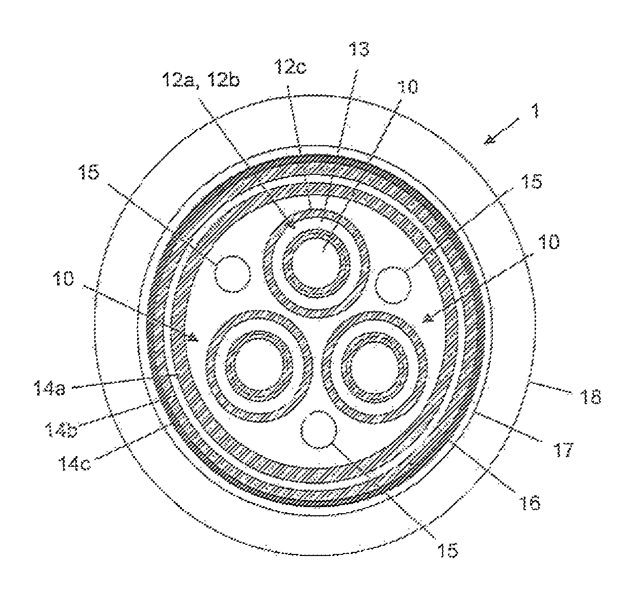
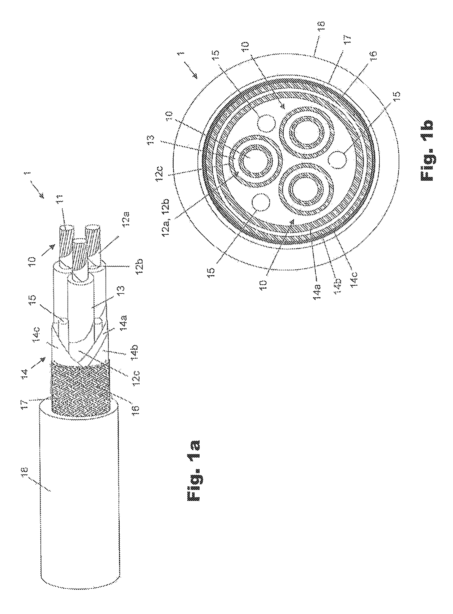
[0050]FIGS. 1a and 1b show a low-voltage electrical cable 1 according to the present invention.

[0051]The electrical cable 1 preferably comprises one or more conductors, for example three conductors 10. Each conductor 10 comprises a plurality of metal wires 11, made of copper or tinned annealed copper. The conductor 10 may be, for example, a Class 2 or Class 5 conductor as defined in the IEC 60228 standard, 3rd edition, 2004-11.

[0052]Around each conductor 10 an insulating coating formed by one or more layers of material which is non-thermally-collapsible up to a temperature of, for example, 1050° C. is provided.

[0053]In the case of the cable 1 of FIG. 1a, the insulating coating of each conductor 10 comprises two discontinuous layers 12a, 12b of inorganic insulating material, for example glass fibre and / or mica. The discontinuous layers 12a, 12b are preferably each in the form of a tape wound on the conductor 10. Advantageously, each of these tapes is wound with an overlap equal to or...

second embodiment

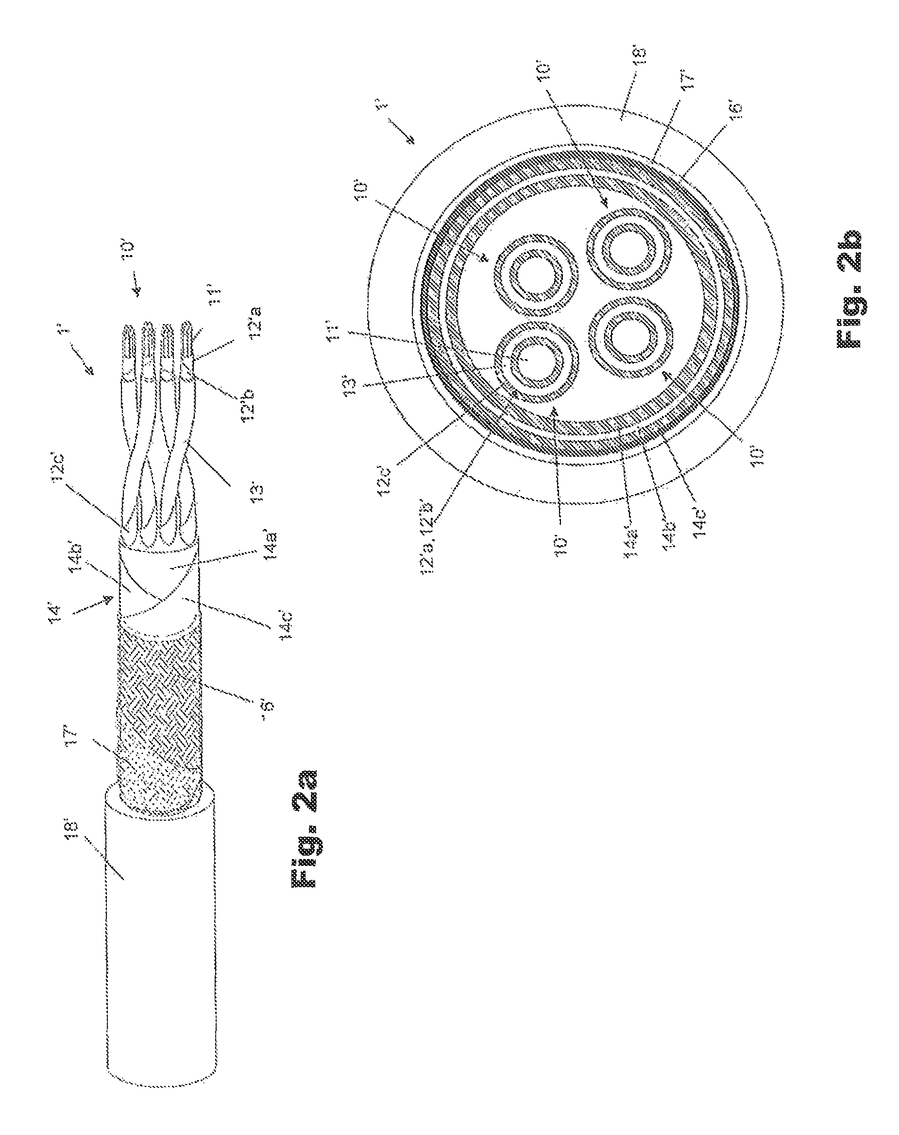
[0069]FIGS. 2a and 2b show a low-voltage electrical cable 1′ according to the present invention.

[0070]The electrical cable 1′ preferably comprises one or more pairs of conductors, for example two pairs of conductors 10′.

[0071]Each conductor 10′ preferably comprises a plurality 11′ of metal wires, made of copper or tinned annealed copper. The conductor 10′ may be, for example, a Class 2 or Class 5 conductor as defined by the IEC 60228 standard, 3rd edition, 2004-11.

[0072]Each conductor 10′ is enclosed by an insulating coating formed by one or more materials which are non-thermally-collapsible up to a temperature of 1050° C., for example.

[0073]The insulating coating of each conductor 10′ is substantially similar, in respect of layers and materials, to the insulating coating of the conductors 10 of the electrical cable 1 shown in FIGS. 1a and 1b; that is, it comprises two discontinuous layers 12′a, 12′b of inorganic insulating material, a layer of ceramifying polymer 13′, and, optional...


PUM

PropertyMeasurementUnit
temperaturesaaaaaaaaaa
temperatureaaaaaaaaaa
temperaturesaaaaaaaaaa

Abstract

An electrical cable includes at least one conductor and a barrier arranged externally to the at least one conductor. The barrier includes two first layers including an inorganic material and a second layer including a polymer-metal composite material, the second layer being interposed between the two first layers. The electrical cable also includes, in an intermediate position between the at least one conductor and the barrier, solely discontinuous layers and/or layers of non-thermally-collapsible materials.

Description

BACKGROUND OF THE INVENTION[0001]1. Field of the Invention[0002]The present invention generally relates to the field of electrical cables. In particular, the present invention relates to an electrical cable resistant to fire, water and mechanical stresses.[0003]2. Description of the Related Art[0004]As is known, an electrical cable resistant to fire (known as a “fire resistant” cable) is a cable configured so as to be capable of continuing to function with acceptable electrical performance even if, owing to a fire, it is exposed to a naked flame for a period of time, at temperatures of up to 800° C.-900° C. or above.[0005]Fire resistant electrical cables are used for various purposes including applications on ships or marine platforms. In these applications, it is necessary to ensure that certain electrical systems (such as lighting, sprinklers, bulkhead sealing systems and the like) will continue to operate for a given period after the outbreak of a fire, as specified, for example,...

Claims


Application Information

Patent Timeline
Patent Type & Authority Patents(United States)
IPC IPC(8): H01B7/18H01B7/282H01B7/28H01B7/295H01B7/02
CPCH01B7/18H01B7/28H01B7/295H01B7/2825Y02A30/14
Inventor SCAGLIONE, ANTONIOSOCCAL, CARLOMAZZUCATO, ALESSANDROBUCCI, RICCARDO
Owner PRYSMIAN SPA
Why Eureka
Try Eureka