Float valve structure
a float valve and structure technology, applied in the field of float valve structure, can solve the problems of increasing the number of portions where sealing needs to be provided, the production cost of float valve according to the related art increases with the increase in the number of portions, and the valve can only offer limited sealing performance, so as to reduce production costs, enhance sealing performance, and facilitate opening of the valv
- Summary
- Abstract
- Description
- Claims
- Application Information
AI Technical Summary
Benefits of technology
Problems solved by technology
Method used
Image
Examples
first embodiment
[0055] the invention will be described with reference to FIGS. 1 to 20.
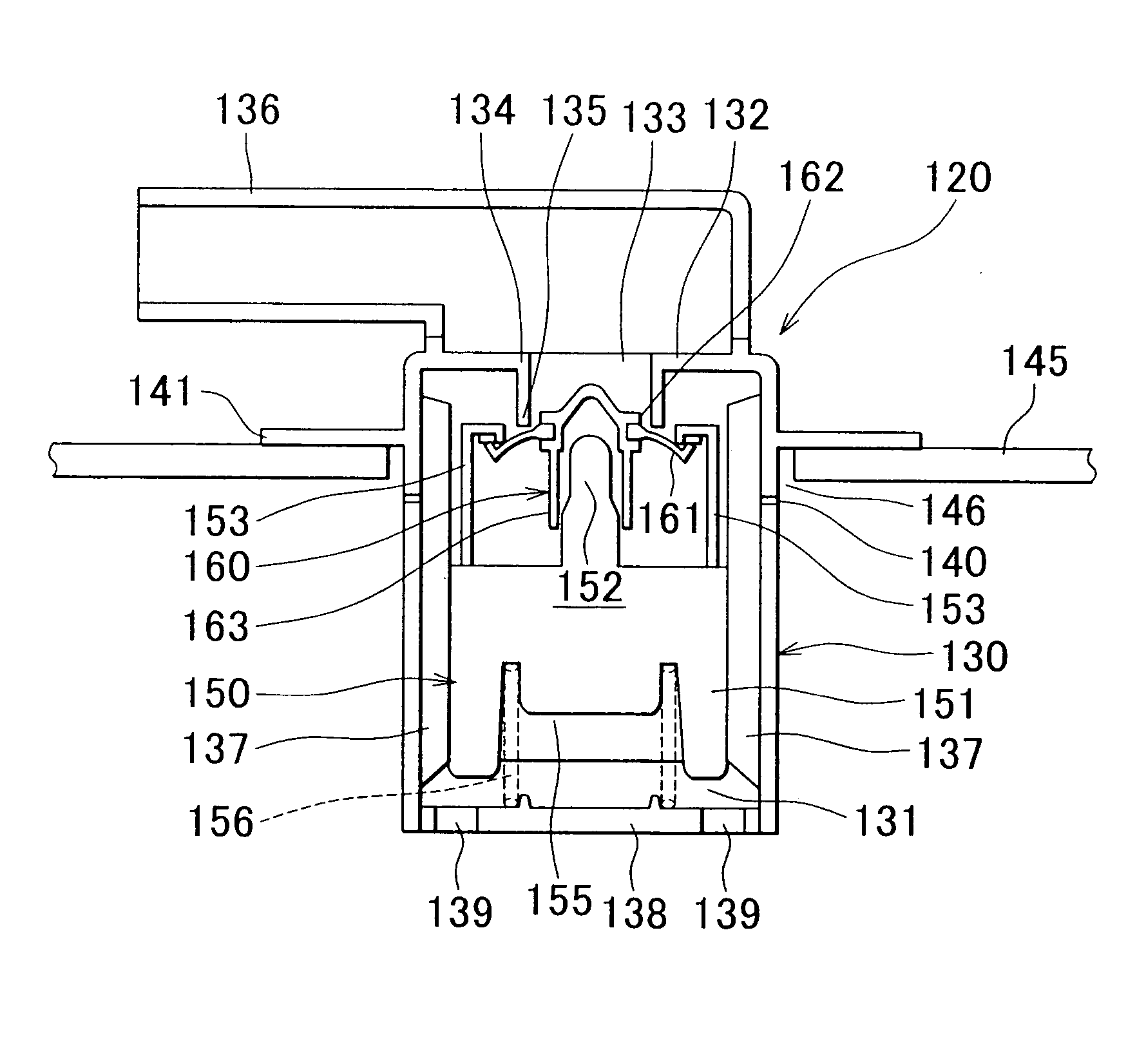
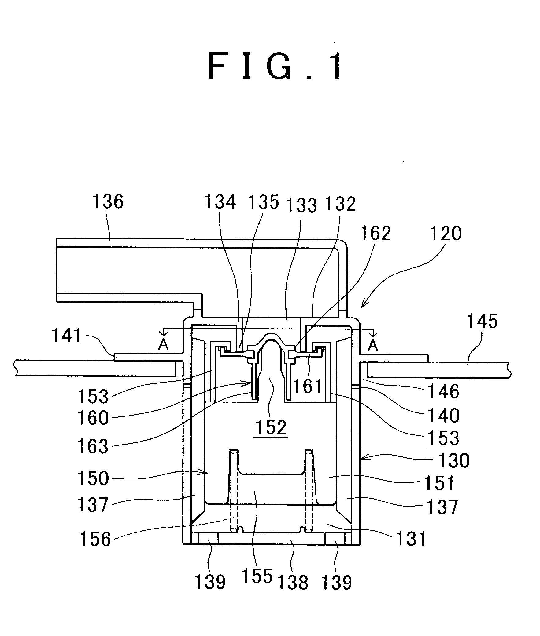
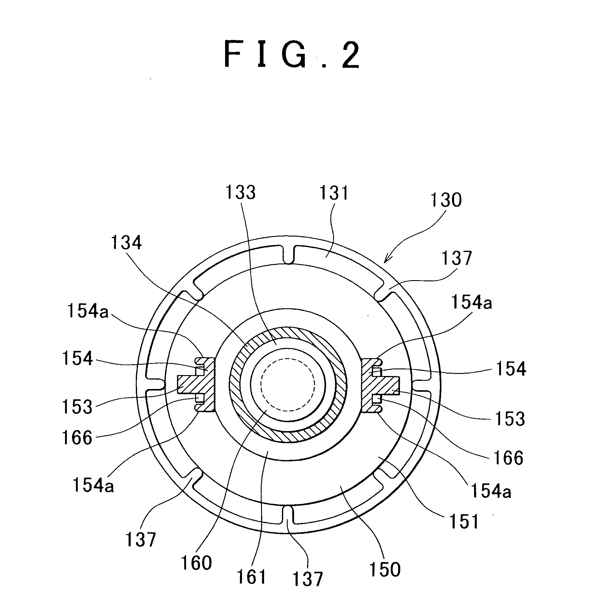
[0056]FIG. 1 illustrates the cross-sectional view of the entirety of a float valve, when a valve is closed. FIG. 2 illustrates the cross-sectional view taken along line A-A in FIG. 1. FIG. 3 illustrates the overall cross-sectional view showing the state where the float has moved downward from the position in FIG. 1, in which the valve is closed, and a part of the valve is moved slightly downward. FIG. 4 illustrates the overall cross-sectional view showing the state where the float has further moved downward from the position in FIG. 3, and the part of the valve is opened. FIG. 5A illustrates the plan view of the valve, and FIG. 5B illustrates the plan view of a valve according to a modified example. FIG. 6A illustrates the plan view and the cross-sectional view of a valve opening member. FIG. 6B illustrates the plan view and the cross-sectional view of a valve opening member according to a modified example. FIG. ...
second embodiment
[0100] Next, the invention will be described with reference to FIGS. 21 to 28.
[0101]FIG. 21 illustrates the cross sectional view of the entirety of a float valve, when the valve is closed. FIG. 22 illustrates the enlarged cross-sectional view showing the portion near a valve support member in FIG. 21. FIG. 23 illustrates the enlarged cross-sectional view showing the state where a part of the valve is forcibly opened by a pressing portion of the valve opening member. FIG. 24 illustrates the state where the valve is fully opened. FIG. 25 illustrates the enlarged cross-sectional view of the valve opening member. The use of the float valve according to the second embodiment of the invention is not particularly limited. In the description below, however, the float valve according to the second embodiment is used for a fuel system for a motor vehicle.
[0102] The float valve 220 includes the case 230, the float 250 arranged in the case 230, the valve support member 60, the flange 241 that ...
PUM
 Abstract
Description
Claims
Application Information
 - R&D
- Intellectual Property
- Life Sciences
- Materials
- Tech Scout
- Unparalleled Data Quality
- Higher Quality Content
- 60% Fewer Hallucinations
Browse by: Latest US Patents, China's latest patents, Technical Efficacy Thesaurus, Application Domain, Technology Topic, Popular Technical Reports.
© 2025 PatSnap. All rights reserved.Legal|Privacy policy|Modern Slavery Act Transparency Statement|Sitemap|About US| Contact US: help@patsnap.com


