Power monitoring system including a wirelessly communicating electrical power transducer

a technology of power monitoring system and wireless communication, which is applied in the direction of electrical testing, measurement devices, instruments, etc., can solve the problems of inability to reliably measure voltage without, the danger of meter boxes that operators must come into contact with, and the problems of existing power monitoring systems

Inactive Publication Date: 2007-01-11
EATON CORP
View PDF16 Cites 66 Cited by
  • Summary
  • Abstract
  • Description
  • Claims
  • Application Information

AI Technical Summary

Problems solved by technology

Existing power monitoring systems present several problems.
First, voltage cannot be reliably measured without being physically connected to the conductor, which typically carries voltages on the order of 120-600 VAC or 1,200-40,000 VAC.
As a result, the meter boxes that operators must come into contact with are dangerous as they are directly connected to the voltage conductors.
The fact that the meter boxes are connected to the voltage conductors present the potential that the voltage could be passed to the communication network when problems arise, which would likely be very harmful to the network and potentially hazardous to the user.
The most common cause of monitoring system failure is errors made in the cable connection process (e.g., phases incorrectly connected).

Method used


Image

  • Power monitoring system including a wirelessly communicating electrical power transducer
  • Power monitoring system including a wirelessly communicating electrical power transducer
  • Power monitoring system including a wirelessly communicating electrical power transducer

Examples


Embodiment Construction

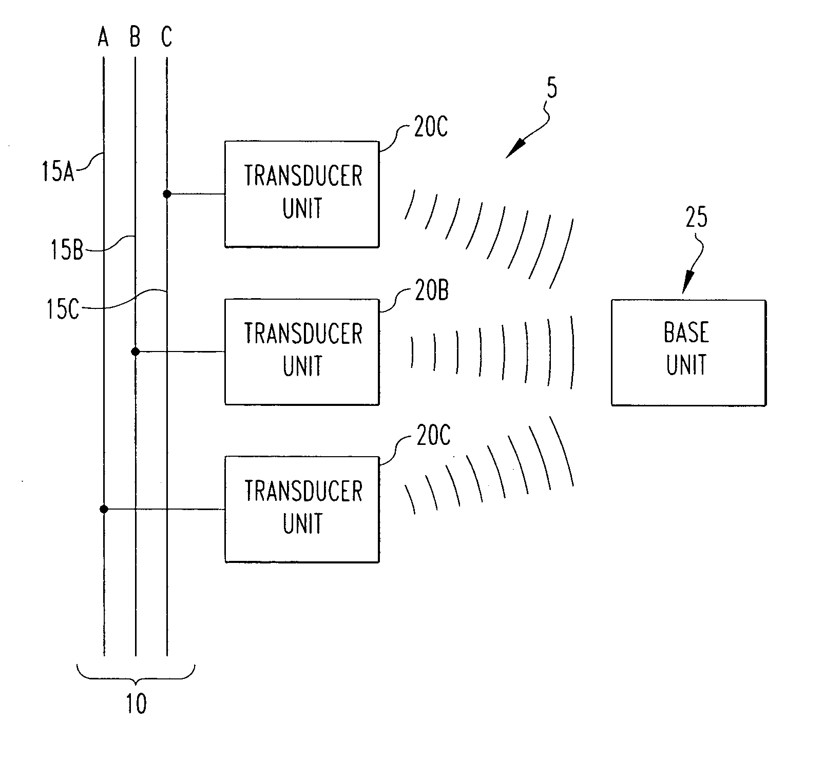
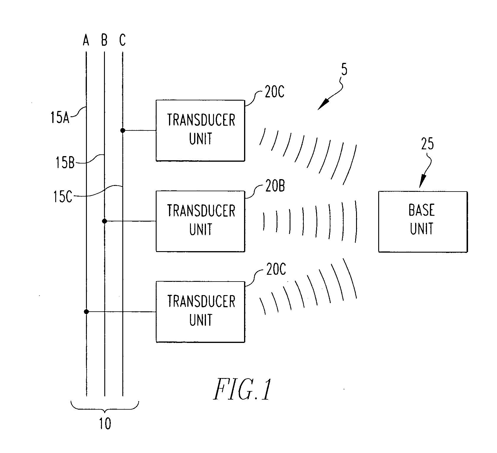
[0019] Referring to FIG. 1, monitoring system 5 is used to monitor and analyze electrical power system 10. Electrical power system 10 includes three phase conductors 15A, 15B and 15C. Although not shown, the electrical power system 10 may include one or both of a ground conductor and a neutral conductor. Although a three-phase power system is shown, the invention is applicable to power systems having one or more phase conductors. As seen in FIG. 1, monitoring system 5 includes three transducers units 20A, 20B, 20C. Each transducer unit 20A, 20B, 20C is operatively coupled, as described below, to a respective phase conductor 15A, 15B, 15C, and may be located in close proximity to or remote from one another. Each transducer unit 20A, 20B, 20C measures the current and voltage of the respective phase conductor 15A, 15B, 15C to which it is coupled. Monitoring system 5 further includes base unit 25, preferably located remotely from each transducer unit 20A, 20B, 20C. The data that is meas...


PUM


Abstract

A system for monitoring an electrical power system includes one or more transducer units, each of which has a current measuring device and a voltage measuring device coupled to a respective one of the phase conductors of the power system, and a transducer wireless communications device. The transducer wireless communications device of each transducer unit transmits the measured current data and voltage data to a base unit. The base unit generates one or more electrical parameters relating to the power system using the received current data and voltage data. Also, a method of monitoring a power system including generating current and voltage data for each phase conductor at a first location, wirelessly transmitting the current and voltage data to a second location, and generating at the second location electrical parameters relating to the power system using the current and voltage data for each phase conductor.

Description

BACKGROUND OF THE INVENTION [0001] 1. Field of the Invention [0002] The present invention relates to systems for monitoring an electrical power system, and in particular to power monitoring systems that utilize one or more wirelessly communicating electrical power transducers. [0003] 2. Background Information [0004] Systems for monitoring alternating current (ac) power systems are well known and typically include discrete analog components which measure ac voltage and current signals from a power system and convert them into direct current (dc) output signals. Such systems also typically include microcomputers for calculating various electrical parameters such as rms currents and voltages, peak currents and voltages, average powers, power factors, alarm limits, over and under voltages, and the like. In addition to monitoring the various electrical parameters of the power system, such monitoring systems also digitally capture portions of the analog waveforms of the power system for h...

Claims


Application Information

Patent Timeline
Patent Type & Authority Applications(United States)
IPC IPC(8): G01R31/04
CPCG01R19/2513G01R15/26
Inventor MAUNEY, WILLIAM M. JR.MANJREKAR, MADHAV D.
Owner EATON CORP
Why Eureka
Try Eureka