Wheel identifying apparatus and tire inflation pressure detecting apparatus with function of wheel identification

a technology of identifying apparatus and detecting apparatus, which is applied in the field of tire inflation pressure, can solve the problems of receiver not being able to identify the wheel, receiver cannot determine whether a pressure signal received by one of the transmitters has been transmitted, and the receiver cannot determine the location of the transmitters (i.e., tires) on the vehicle, so as to achieve automatic and accurate detection of the location

Active Publication Date: 2007-01-11
DENSO CORP
View PDF22 Cites 65 Cited by
  • Summary
  • Abstract
  • Description
  • Claims
  • Application Information

AI Technical Summary

Benefits of technology

[0016] It is, therefore, an object of the present invention to provide a wheel identifying apparatus for a vehicle which can automatically and accurately identify, for each of the transmitters (or transceivers), the wheel on which it is located without performing the time-consuming ID signal registration task.
[0017] It is a further object of the present invention to provide a wheel identifying apparatus for a vehicle which can automatically and accurately identify, for each of the transmitters (or transceivers), the wheel on which it is located without using any ID signals.
[0018] It is a still further object of the present invention to provide a tire inflation pressure detecting apparatus for a vehicle which can automatically and accurately detect the locations as well as the inflation pressure of tires on the vehicle.

Problems solved by technology

However, it is impossible for the receiver to determine whether a pressure signal received thereby has been transmitted by one of the transmitters or by an external transmitter.
Moreover, it is also impossible for the receiver to detect the locations of the transmitters (i.e., the tires) on the vehicle.
In other words, the receiver cannot identify the wheel on which the transmitter having transmitted a pressure signal and the tire whose inflation pressure is indicated by the pressure signal are located.
However, the registration of the ID signals in the receiver is a time-consuming task, and thus it is desired to automatically perform the registration task.

Method used


Image

  • Wheel identifying apparatus and tire inflation pressure detecting apparatus with function of wheel identification
  • Wheel identifying apparatus and tire inflation pressure detecting apparatus with function of wheel identification
  • Wheel identifying apparatus and tire inflation pressure detecting apparatus with function of wheel identification

Examples


first embodiment

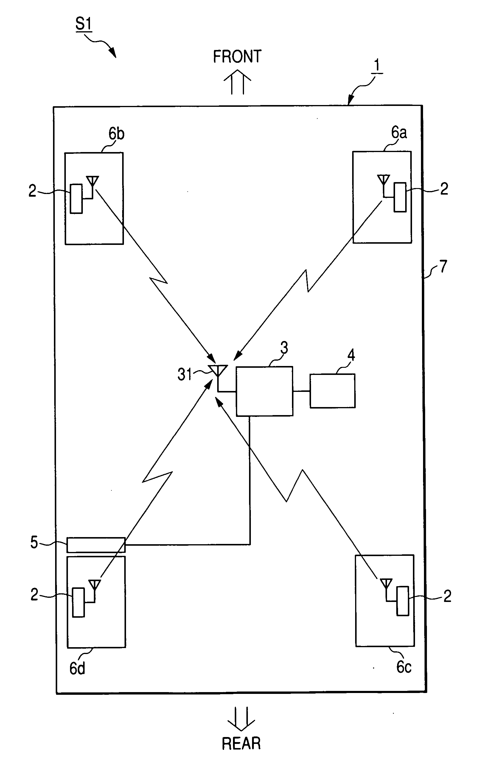
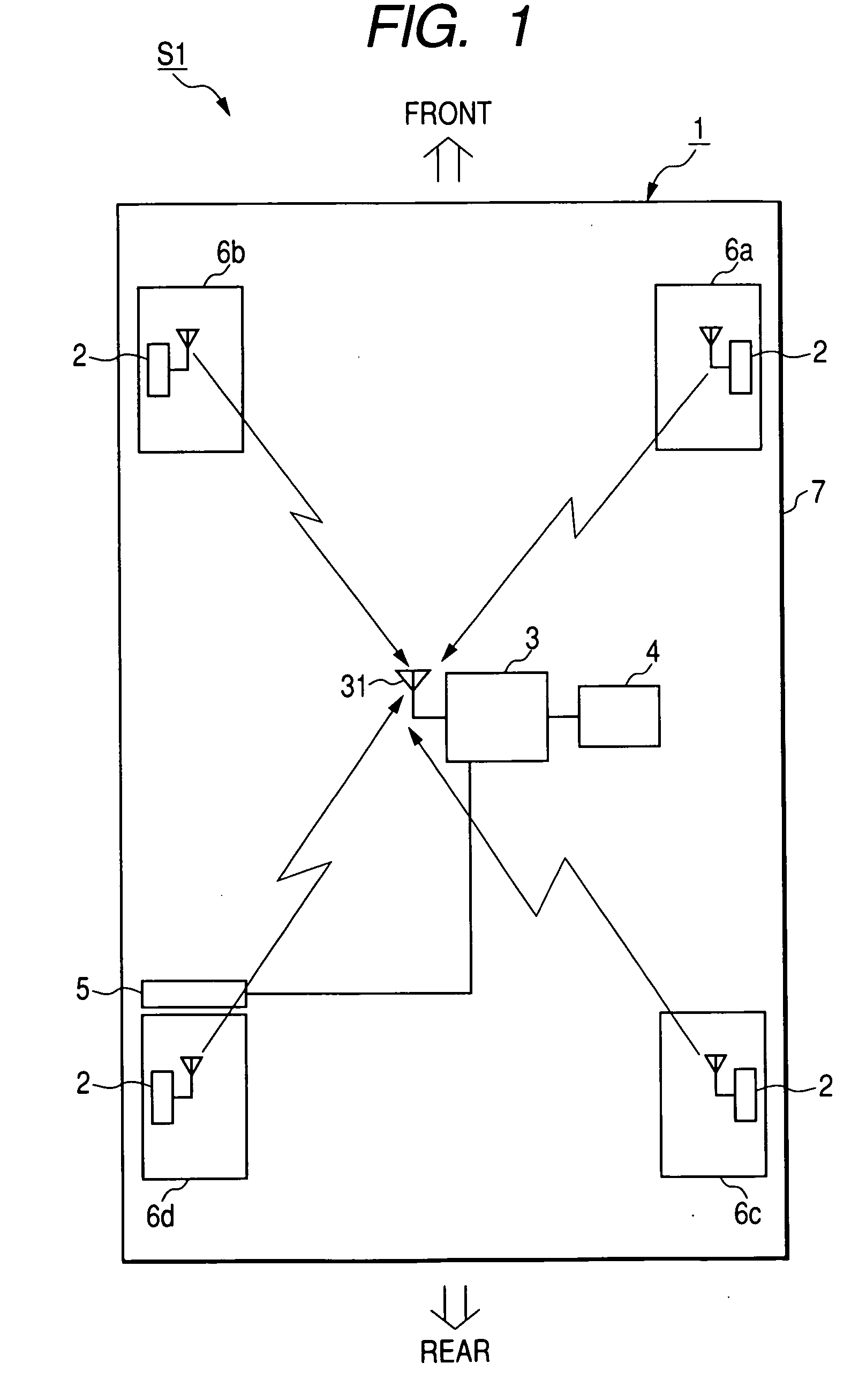
[0103]FIG. 1 shows the overall configuration of a tire inflation pressure detecting apparatus S1 according the first embodiment of the invention.

[0104] The tire inflation pressure detecting apparatus S1 is installed to a vehicle 1 and configured to detect the inflation pressure of four tires each of which is fitted on one of four wheels 6a-6d of the vehicle 1 (i.e., the FR wheel 6a, the FL wheel 6b, the RR wheel 6c, and the RL wheel 6d).

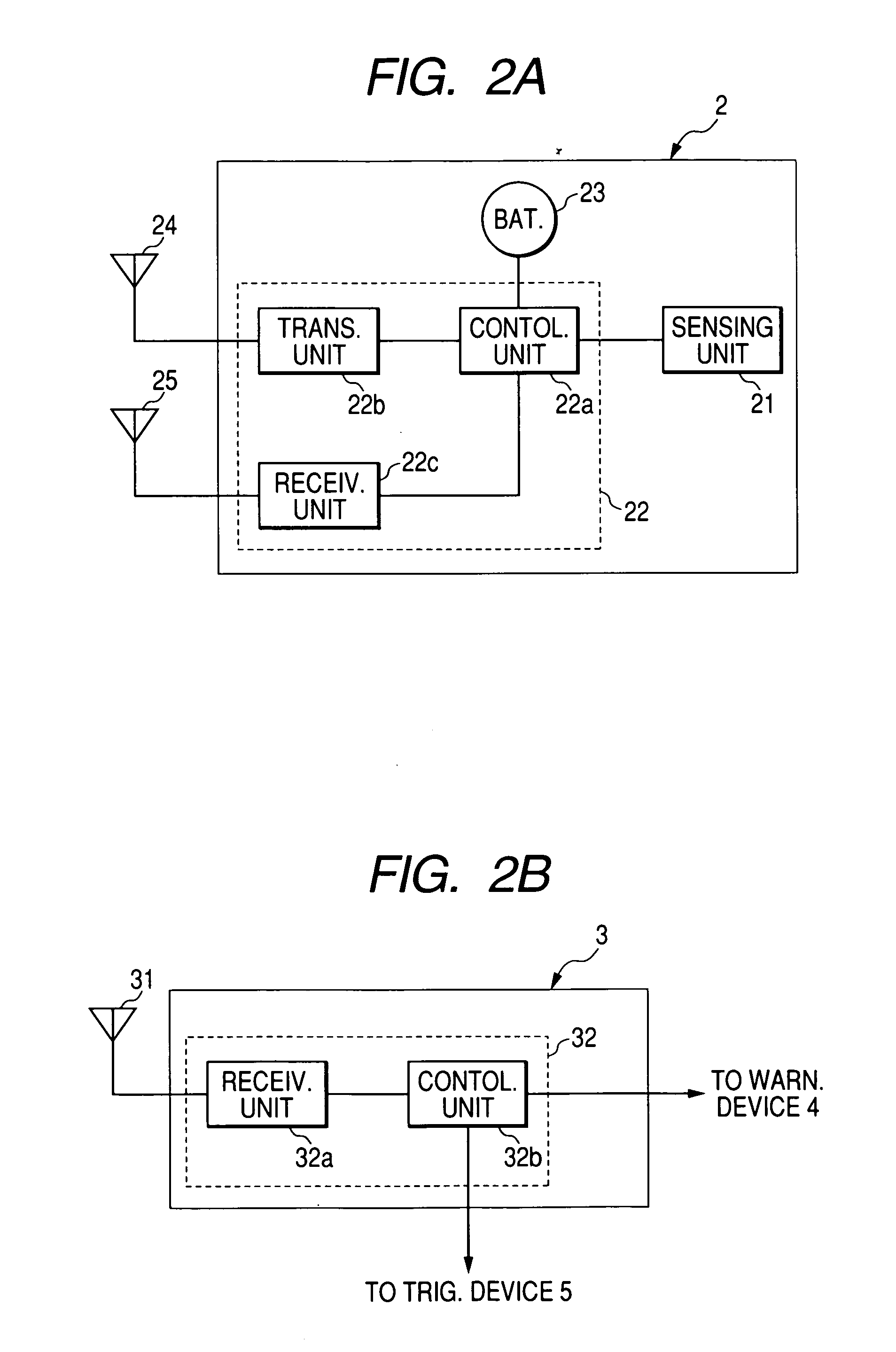
[0105] As shown in FIG. 1, the tire inflation pressure detecting apparatus S1 includes four transceivers 2, a receiver 3, a warning device 4, and a triggering device 5.

[0106] Each of the transceivers 2 is mounted on one of the four wheels 6a-6d, so as to have association with the tire on the one of the wheels 6a-6d.

[0107] Each transceiver 2 works to sense the inflation pressure of the associated tire and transmit a frame that contains tire pressure information indicative of the sensed inflation pressure of the associated tire.

[0108] Referring to...

second embodiment

[0162] This embodiment illustrates a tire inflation pressure detecting apparatus S2 which has almost the same configuration as the tire inflation pressure detecting apparatus S1 according to the previous embodiment. Accordingly, only the differences therebetween will be described hereinafter.

[0163] In the previous embodiment, each of the four transceivers 2 receives the trigger signal transmitted by the triggering device 5 and transmits the frame containing the signal strength information indicative of the strength of the trigger signal at the transceiver 2; the receiver 3 identifies, for each of the frames received from the four transceivers 2, the wheel on which the transceiver 2 having transmitted the frame is mounted based on the signal strength information contained in the frame.

[0164] In comparison, in the present embodiment, the triggering device 5 outputs the trigger signal with a limited strength, so that one of the four transceivers 2 cannot receive the trigger signal.

[...

third embodiment

[0177] This embodiment illustrates a tire inflation pressure detecting apparatus S3 which has almost the same configuration as the tire inflation pressure detecting apparatus S1 according to the first embodiment. Accordingly, only the differences therebetween will be described hereinafter.

[0178] In the first embodiment, there is provided only the single triggering device 5 in the tire inflation pressure detecting apparatus S1. Further, the trigger signal transmitted by the triggering device 5 is received by all the transceivers 2.

[0179] In comparison, with reference to FIG. 9, there are provided two triggering devices 5a and 5b in the tire inflation pressure detecting apparatus S3. Further, the trigger signal transmitted by each of the triggering devices 5a and 5b is received by only three of the transceivers 2.

[0180] Specifically, as shown in FIG. 9, the triggering device 5a is arranged in close vicinity to the RL wheel 6d, while the triggering device 5b is arranged in close vic...


PUM


Abstract

A wheel identifying apparatus according to the present invention includes a plurality of transceivers, a triggering device, a receiver, and a wheel identifier. Each of the transceivers is located on one of a plurality of wheels of a vehicle and works to receive a trigger signal and transmit a response signal in response to receipt of the trigger signal. The triggering device is located on a body of the vehicle at different distances from the transceivers and works to transmit the trigger signal. The receiver works to receive the response signals transmitted by the transceivers. The wheel identifier is operatively connected to the receiver and works to identify, for each of the response signals received by the receiver, the wheel on which the transceiver having transmitted the response signal is located using the fact that strengths of the trigger signal at the transceivers are different from each other.

Description

CROSS-REFERENCE TO RELATED APPLICATION [0001] This application is based on and claims priority from Japanese Patent Applications No. 2005-197497, filed on Jul. 6, 2005, and No. 2005-198703, filed on Jul. 7, 2005, the contents of which are hereby incorporated by reference into this application. BACKGROUND OF THE INVENTION [0002] 1. Technical Field of the Invention [0003] The present invention relates generally to tire inflation pressure detecting apparatuses for detecting the inflation pressure of tires on a vehicle and tire location detecting apparatuses for automatically detecting the locations of tires on a vehicle. [0004] More particularly, the invention relates to a direct-type tire inflation pressure detecting apparatus which has a function of wheel identification. [0005] 2. Description of the Related Art [0006] Conventional direct-type tire inflation pressure detecting apparatuses generally include a plurality of transmitters and a receiver. [0007] Each of the transmitters is ...

Claims


Application Information

Patent Timeline
Patent Type & Authority Applications(United States)
IPC IPC(8): G08B26/00
CPCB60C23/045B60C23/0464B60C23/0444B60C23/044B60C23/0416G01L17/00B60C23/00
Inventor MORI, MASASHIOKUMURA, RYOZOSAITO, HIDEKIWATABE, NOBUYA
Owner DENSO CORP
Why Eureka
Try Eureka