High-end equipment manufactured three-degree-of-freedom manipulator auxiliary positioning device

A technology that assists positioning and degrees of freedom, applied in the field of manipulators, can solve the problems of manipulator positioning effect, which greatly affects the level of operators, difficult to guarantee the work efficiency and quality of manipulators, time-consuming and labor-intensive, etc., to improve work efficiency and quality, practical The effect of improving performance and improving accuracy

Inactive Publication Date: 2021-05-07
董希利
View PDF8 Cites 0 Cited by
  • Summary
  • Abstract
  • Description
  • Claims
  • Application Information

AI Technical Summary

Problems solved by technology

[0005] Aiming at the deficiencies of the prior art, the present invention provides a three-degree-of-freedom manipulator auxiliary positioning device for high-end equipment manufacturing, which has the advantages of automatic and accurate detection, accurate positioning, time-saving and labor-saving, simple and convenient operation, and high operating efficiency, and solves the existing problems. The manipulator generally needs real-time precise positioning when carrying goods and operating tools, but the existing manipulators generally use cameras and position sensors for spatial position positioning, but this depends on the precise installation and commissioning of the operator. Such a process is time-consuming and labor-intensive. At the same time, the positioning effect of the manipulator is greatly affected by the level of the operator. In actual production, it is difficult to guarantee the working efficiency and quality of the manipulator, which also increases the cost of later maintenance and use.

Method used


Image

  • High-end equipment manufactured three-degree-of-freedom manipulator auxiliary positioning device
  • High-end equipment manufactured three-degree-of-freedom manipulator auxiliary positioning device
  • High-end equipment manufactured three-degree-of-freedom manipulator auxiliary positioning device

Examples


Embodiment Construction

[0026] The following will clearly and completely describe the technical solutions in the embodiments of the present invention with reference to the accompanying drawings in the embodiments of the present invention. Obviously, the described embodiments are only some of the embodiments of the present invention, not all of them. Based on the embodiments of the present invention, all other embodiments obtained by persons of ordinary skill in the art without making creative efforts belong to the protection scope of the present invention.

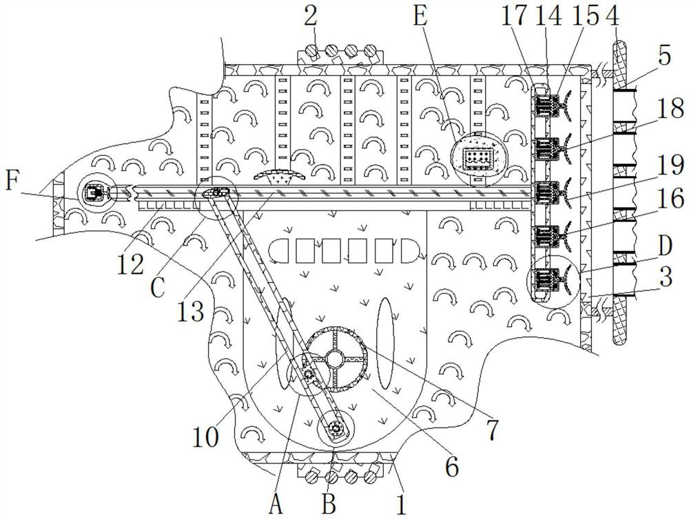
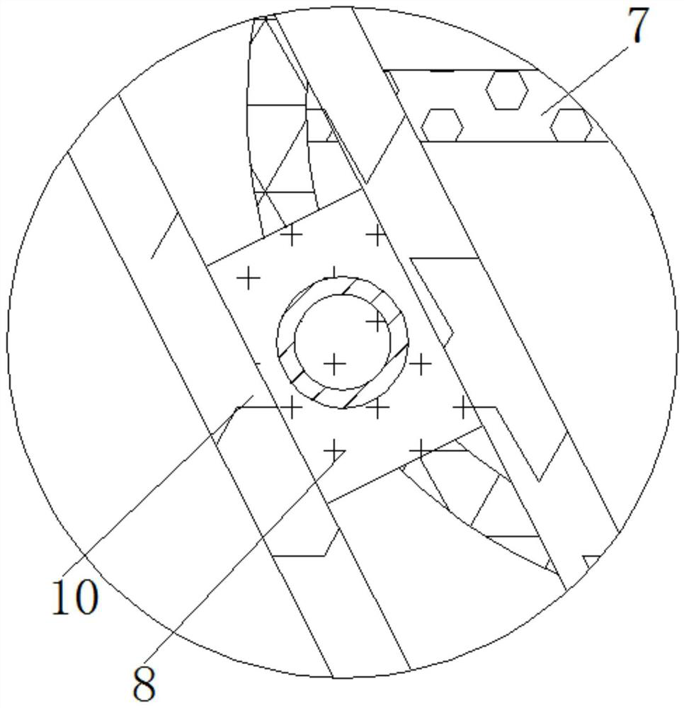
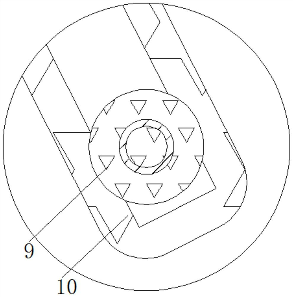
[0027] see Figure 1-7 , a three-degree-of-freedom manipulator auxiliary positioning device for high-end equipment manufacturing, including a housing 1, a button 2 is fixedly connected to the outside of the housing 1, an outlet 3 is opened on the surface of the housing 1, a mounting plate 4 is fixedly connected to the outside of the housing 1, and the housing 1 There are action ports on the surface of the body, the number of action ports is not l...


PUM


Abstract

The invention relates to the technical field of manipulators and discloses a high-end equipment manufactured three-degree-of-freedom manipulator auxiliary positioning device comprising a shell. Buttons are fixedly connected outside the shell; an outlet is formed in the surface of the shell; a mounting plate is fixedly connected outside the shell; and detection sleeves are fixedly connected outside the mounting plate. Through the interaction of the shell, the buttons, the outlet, the mounting plate, the detection sleeves, a connecting plate, a rotating wheel, a moving block, a limiting block, sliding rods, an adapter block, sliding rails, a closed shell, movable rods, touch plates, bearing plates, positioning plates, a photosensitive assembly and a detection assembly, the practicability of the manipulator can be further improved; and meanwhile, the influence on the actual use of the manipulator caused by the experience level of operators on the mounting and debugging of the manipulator can be effectively reduced, so that the working efficiency and quality of the manipulator are effectively improved, and the later maintenance and use cost of the manipulator can be greatly reduced.

Description

technical field [0001] The invention relates to the technical field of manipulators, in particular to a three-degree-of-freedom manipulator auxiliary positioning device for high-end equipment manufacturing. Background technique [0002] A manipulator is an automatic operating device that can imitate certain movement functions of the human hand and arm to grab, carry objects or operate tools according to a fixed program. It is characterized in that it can be programmed to complete various expected operations. Combining the advantages of both humans and robots, manipulators are the earliest industrial robots. Existing manipulators generally need real-time precise positioning when carrying goods and operating tools, but existing manipulators generally use cameras and position sensors. To locate the position of the space, but it depends on the precise installation and debugging of the operator. This process is time-consuming and laborious. At the same time, the positioning effec...

Claims


Application Information

Patent Timeline
Patent Type & Authority Applications(China)
IPC IPC(8): B25J9/16B25J19/00
CPCB25J9/16B25J19/00B25J9/1679B25J9/1694
Inventor 董希利
Owner 董希利
Why Eureka
Try Eureka