Fire extinguishing pipe cutting device for firefighting

A technology of cutting device and fire extinguishing pipe, applied in sawing machine, metal sawing equipment, metal processing equipment, etc., can solve the problems of uneven cutting of nozzles, time-consuming and laborious fire extinguishing pipe length, etc.

Active Publication Date: 2018-09-21
淮安市淮安区综合检验检测中心
View PDF5 Cites 10 Cited by
  • Summary
  • Abstract
  • Description
  • Claims
  • Application Information

AI Technical Summary

Problems solved by technology

[0005] In order to overcome the disadvantages of manual cutting of fire extinguishing pipes in the prior art, which is time-consuming and laborious, and the length of fire extinguishing pipes and nozzles are not uniformly cut, the techni

Method used


Image

  • Fire extinguishing pipe cutting device for firefighting
  • Fire extinguishing pipe cutting device for firefighting
  • Fire extinguishing pipe cutting device for firefighting

Examples


Example Embodiment

[0022] Example 1

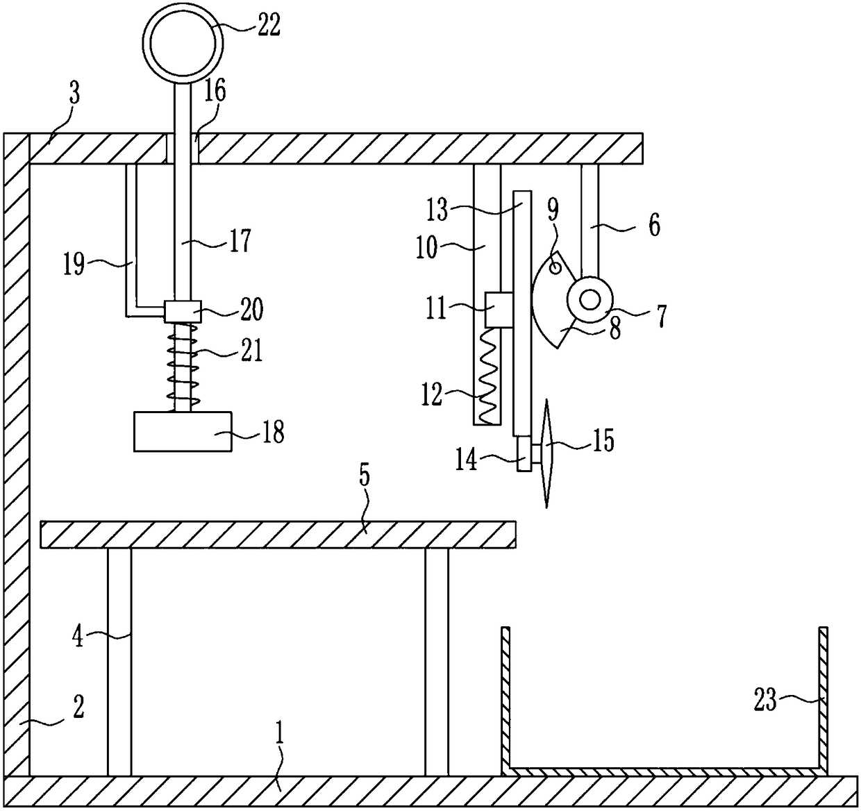
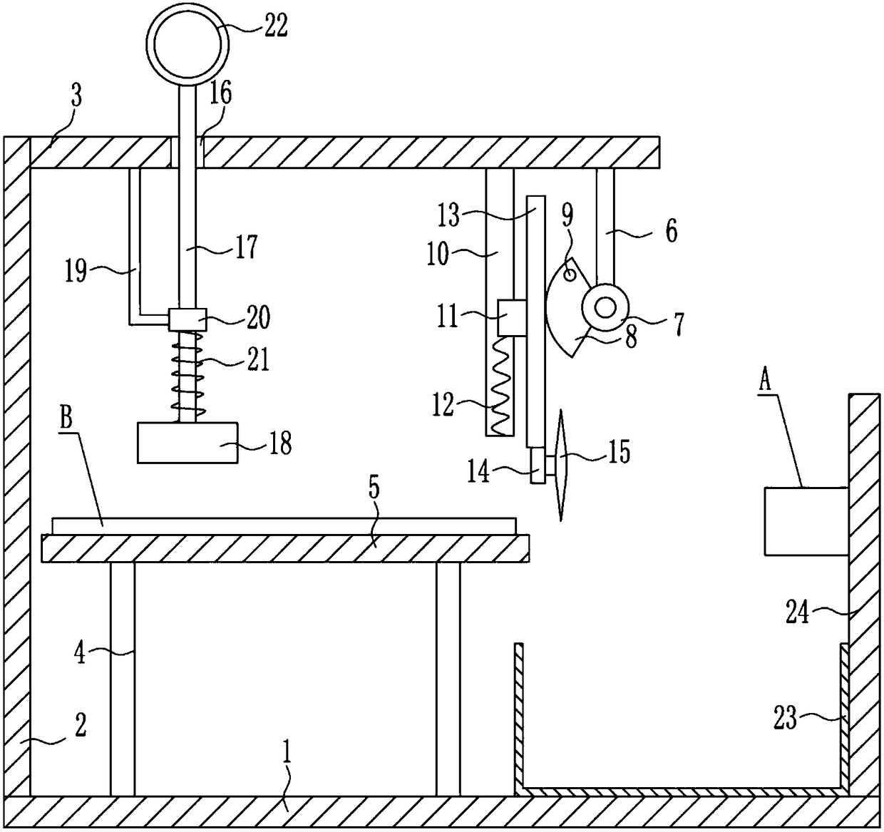
[0023] A fire extinguishing pipe cutting device for fire fighting, such as Figure 1-5 As shown, it includes a bottom plate 1, a left bracket 2, a top plate 3, a supporting rod 4, a placing table 5, a first supporting rod 6, a rotating shaft 7, a sector gear 8, a rotating rod 9, a first sliding rail 10, and a first sliding block 11. The first spring 12, the rack 13, the first motor 14, the saw disk 15, the guide rod 17, the arc pressing plate 18, the second support rod 19, the guide sleeve 20, the second spring 21, the pull ring 22 and the collection box 23. The upper left part of the bottom plate 1 is fixedly connected with the left bracket 2, the upper right part of the left bracket 2 is fixedly connected with the top plate 3, and the upper left part of the bottom plate 1 is fixedly connected with two support rods 4, and the two support rods 4 are arranged left and right. , The support rods 4 are all located on the right of the left bracket 2, the top of the...

Example Embodiment

[0024] Example 2

[0025] A fire extinguishing pipe cutting device for fire fighting, such as Figure 1-5 As shown, it includes a bottom plate 1, a left bracket 2, a top plate 3, a supporting rod 4, a placing table 5, a first supporting rod 6, a rotating shaft 7, a sector gear 8, a rotating rod 9, a first sliding rail 10, and a first sliding block 11. The first spring 12, the rack 13, the first motor 14, the saw disk 15, the guide rod 17, the arc pressing plate 18, the second support rod 19, the guide sleeve 20, the second spring 21, the pull ring 22 and the collection box 23. The upper left part of the bottom plate 1 is fixedly connected with the left bracket 2, the upper right part of the left bracket 2 is fixedly connected with the top plate 3, and the upper left part of the bottom plate 1 is fixedly connected with two support rods 4, and the two support rods 4 are arranged left and right. , The support rods 4 are all located on the right of the left bracket 2, the top of the...

Example Embodiment

[0027] Example 3

[0028] A fire extinguishing pipe cutting device for fire fighting, such as Figure 1-5 As shown, it includes a bottom plate 1, a left bracket 2, a top plate 3, a supporting rod 4, a placing table 5, a first supporting rod 6, a rotating shaft 7, a sector gear 8, a rotating rod 9, a first sliding rail 10, and a first sliding block 11. The first spring 12, the rack 13, the first motor 14, the saw disk 15, the guide rod 17, the arc pressing plate 18, the second support rod 19, the guide sleeve 20, the second spring 21, the pull ring 22 and the collection box 23. The upper left part of the bottom plate 1 is fixedly connected with the left bracket 2, the upper right part of the left bracket 2 is fixedly connected with the top plate 3, and the upper left part of the bottom plate 1 is fixedly connected with two support rods 4, and the two support rods 4 are arranged left and right. , The support rods 4 are all located on the right of the left bracket 2, the top of the...


PUM


Abstract

The invention relates to a cutting device, in particular to a fire extinguishing pipe cutting device for firefighting. The fire extinguishing pipe cutting device for firefighting aims at achieving thetechnical effects that a fire extinguishing pipe does not need to be manually cut, time and labor are saved and length and pipe orifice cutting of the fire extinguishing pipe is uniform. According tothe technical scheme, the fire extinguishing pipe cutting device for firefighting comprises a bottom plate, a left support, a top plate, supporting rods, a placing table, a first supporting rod, a rotating shaft and the like; and the left support is fixedly connected to the left portion of the upper side of the bottom plate, the top plate is fixedly connected to the upper portion of the right side of the left support, the two supporting rods are fixedly connected to the left portion of the upper side of the bottom plate, the two supporting rods are arranged left and right, and the supportingrods are both located on the right of the left support. The effects that the fire extinguishing pipe does not need to be manually cut, time and labor are saved and length and pipe orifice cutting of the fire extinguishing pipe is uniform are achieved, the position of the fire extinguishing pipe can be better fixed through the arrangement of a third sliding rail, a third sliding block, a buffer plate and a fourth spring, and cutting of the fire extinguishing pipe is more uniform.

Description

Technical field [0001] The invention relates to a cutting device, in particular to a fire extinguishing pipe cutting device for fire fighting. Background technique [0002] The plastic-coated fire pipe uses steel pipe as the base pipe. The outer wall is coated with high-adhesion, impact resistance, anti-corrosion and weather-resistant thermosetting powder coating, and the inner wall is coated with high-adhesion, anti-corrosion, food-grade sanitary thermosetting powder coating. The plastic-coated fire hose is made by sandblasting chemical double pre-treatment, pre-heating, internal coating, external coating, curing, post-treatment and other processes. It is a cost-effective product upgraded from traditional steel-plastic pipes and galvanized pipes. . The product has passed the fire protection certification of the National Chemical Building Material Testing Center. [0003] In the existing fire extinguishing pipe cutting technology, it is necessary to manually cut the fire extingui...

Claims


Application Information

Patent Timeline
IPC IPC(8): B23D45/12
CPCB23D45/12
Inventor 李风花陈涛季莹
Owner 淮安市淮安区综合检验检测中心
Why Eureka
Try Eureka