Clock circuit and clock signal transmission method thereof

A clock circuit and clock signal technology, which is applied in the direction of reducing power, logic circuits, and generating/distributing signals through control/clock signals, can solve the problems of long clock signal propagation path, clock delay and large power consumption, and achieve shortening Effect of clock path, reduction of clock error, and reduction of transmission delay

Active Publication Date: 2017-07-28
HUAWEI TECH CO LTD
View PDF6 Cites 15 Cited by
  • Summary
  • Abstract
  • Description
  • Claims
  • Application Information

AI Technical Summary

Problems solved by technology

When a clock circuit with a traditional structure is used in a digital integrated circuit, too many logic units on the clock path in the clock circuit will make the propagation path of the clock signal too long, resulting in a comparison of clock delay and power consumption on each clock path Big

Method used


Image

  • Clock circuit and clock signal transmission method thereof
  • Clock circuit and clock signal transmission method thereof
  • Clock circuit and clock signal transmission method thereof

Examples


Embodiment Construction

[0038] The following will clearly and completely describe the technical solutions in the embodiments of the present invention with reference to the accompanying drawings in the embodiments of the present invention. Obviously, the described embodiments are some of the embodiments of the present invention, but not all of them. Based on the embodiments of the present invention, all other embodiments obtained by persons of ordinary skill in the art without creative efforts fall within the protection scope of the present invention.

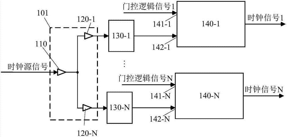
[0039] The application scenarios of the clock circuit in the embodiment of the present invention will be described below with an example. A digital integrated circuit integrating the clock circuit of the embodiment of the present invention can constitute a processor. The processing of the processor needs to be driven by periodic clock pulses, that is, after the clock signal is input to the clock circuit, it is transmitted through the clock circuit, and...


PUM


Abstract

The invention provides a clock circuit and a clock signal transmission method thereof. The clock circuit comprises a buffer module, N multiplexers and N clock gating cells, wherein the buffer module comprises an input end and N output ends, and is used for enhancing the driving capabilities of clock signals received at the input end and outputting clock signals of which the driving capabilities are enhanced from the N output ends; the N output ends are connected with data ends of the N clock gating cells one by one; output ends of the N multiplexers are connected with enabling ends of the N clock gating cells one by one; and the clock gating cells are used for outputting the clock signals from the output ends according to frequency division logic signals or gating logic signals received by the enabling ends from the output ends of corresponding multiplexers and the clock signals received by the data ends from the output ends of the buffer module. Through the technical scheme of the invention, a clock path can be shortened; the transmission delay of a clock source signal is reduced; and the power consumption of the clock circuit is lowered.

Description

technical field [0001] The invention relates to the field of circuits, in particular to a clock circuit and a method for transmitting a clock signal. Background technique [0002] In a digital integrated circuit, the data transmission between each unit is controlled synchronously by a clock signal. When a clock circuit with a traditional structure is used in a digital integrated circuit, too many logic units on the clock path in the clock circuit will make the propagation path of the clock signal too long, resulting in a comparison of clock delay and power consumption on each clock path Big. Contents of the invention [0003] Embodiments of the present invention provide a clock circuit and a method for transmitting a clock signal using the clock circuit, which can reduce clock delay and reduce power consumption of the clock circuit. [0004] In a first aspect, a clock circuit is provided, including a buffer module, N first multiplexers, and N clock gating units, where N ...

Claims


Application Information

Patent Timeline
Patent Type & Authority Applications(China)
IPC IPC(8): H03K5/15
CPCH03K5/15H03K21/026G06F1/06G06F1/10H03K19/0016H03K19/0175H03K19/1737H03K2217/0054G06F30/396G06F5/16
Inventor 杨胜利黄兴
Owner HUAWEI TECH CO LTD
Why Eureka
Try Eureka