Wind Guiding Hood Structure For Wind Power Generation

a wind guiding hood and wind power technology, applied in the direction of wind energy generation, mechanical equipment, machines/engines, etc., can solve the problems of ineffective absorption of large wind energy, partition cannot provide a large wind surface, so as to achieve a larger wind load and large wind load

Inactive Publication Date: 2007-01-11
JETPRO TECH
View PDF10 Cites 45 Cited by
  • Summary
  • Abstract
  • Description
  • Claims
  • Application Information

AI Technical Summary

Benefits of technology

[0007] Therefore, the present invention is to overcome the foregoing shortcomings and avoid the existing deficiencies of the prior art by providing a wind guiding hood for wind power generation, wherein the wind guiding hood can be adjusted according to a change in wind direction and turned to adjust the wind surface, so that the wind guiding hood can obtain a larger wind load for the turbine to generate electric power.
[0008] The improved wind guiding hood for wind power generation of the invention comprises: a frame, a wind guiding hood, a turbine and a wind direction detector. The turbine is installed in the wind guiding hood, and the wind guiding hood is pivotally connected into the frame. After the wind direction detector installed on the wind guiding hood detects a change in wind direction, a correct wind direction signal is transmitted to an actuator installed on the frame to drive the actuator to control the turning direction of the wind guiding hood and adjust the wind surface, so that the wind guiding hood can obtain a larger wind load for the turbine to generate electric power.

Problems solved by technology

However, the wind direction is not necessarily coming from the front side, and thus the positions of the windward opening and leeward opening cannot be changed according to the wind direction after they are fixed at predetermined positions.
When wind blows from the side, the wind collecting partition cannot have provide a larger wind surface, and the vane cannot absorb larger wind energy effectively.

Method used


Image

  • Wind Guiding Hood Structure For Wind Power Generation
  • Wind Guiding Hood Structure For Wind Power Generation
  • Wind Guiding Hood Structure For Wind Power Generation

Examples


Embodiment Construction

[0015] The technical characteristics, features and advantages of the present invention will become apparent in the following detailed description of the preferred embodiments with reference to the accompanying drawings. However, the drawings are provided for reference and illustration only and are not intended for limiting the scope of the invention.

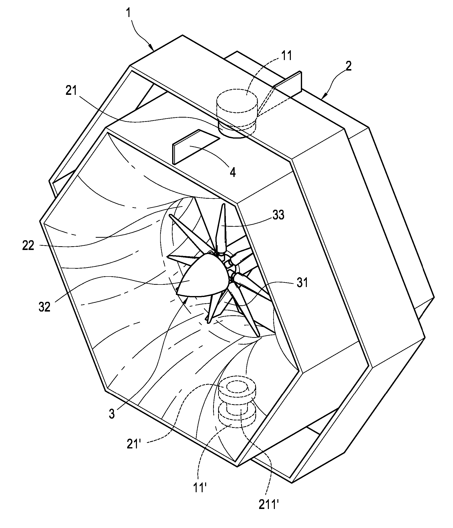
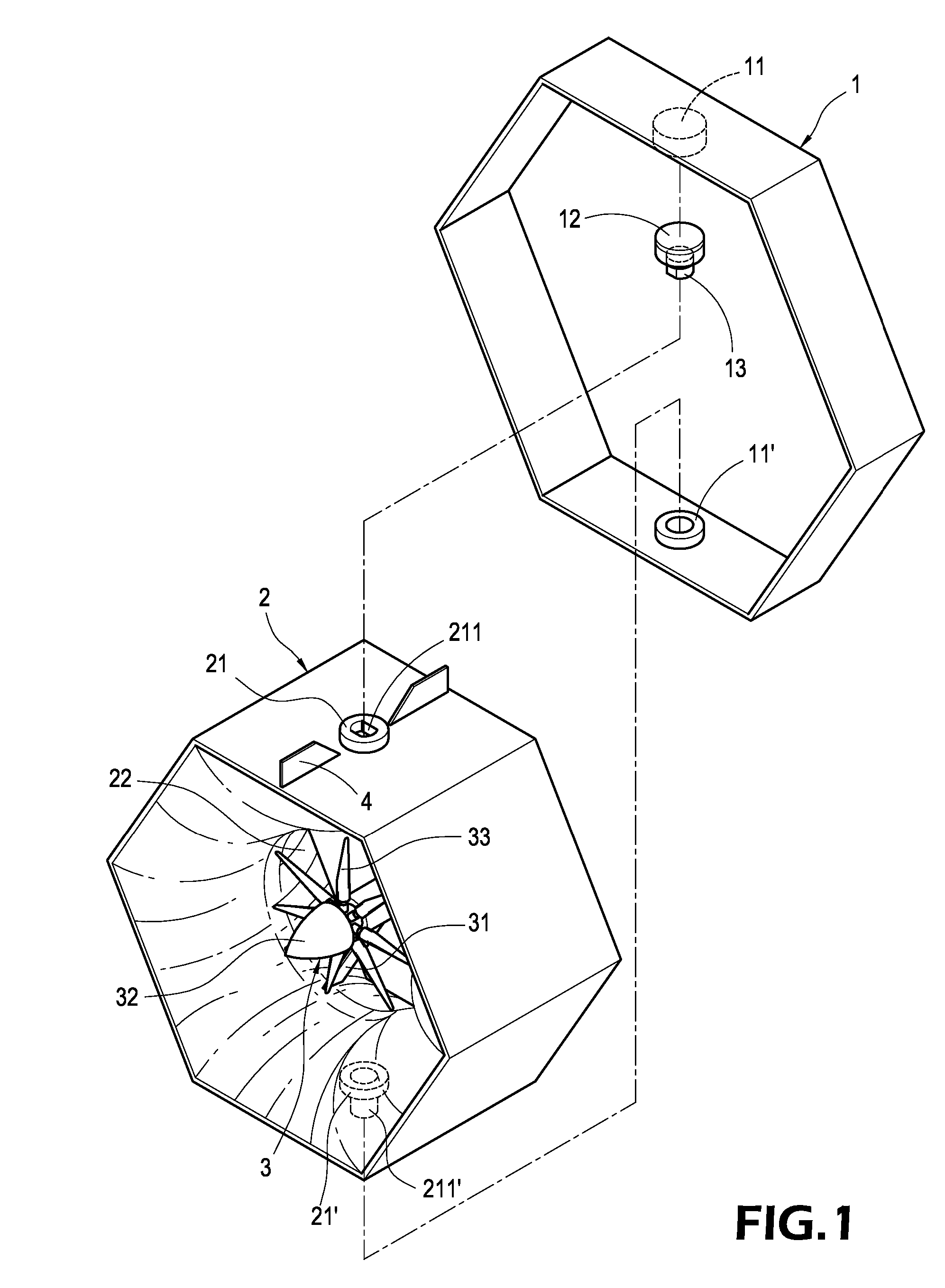
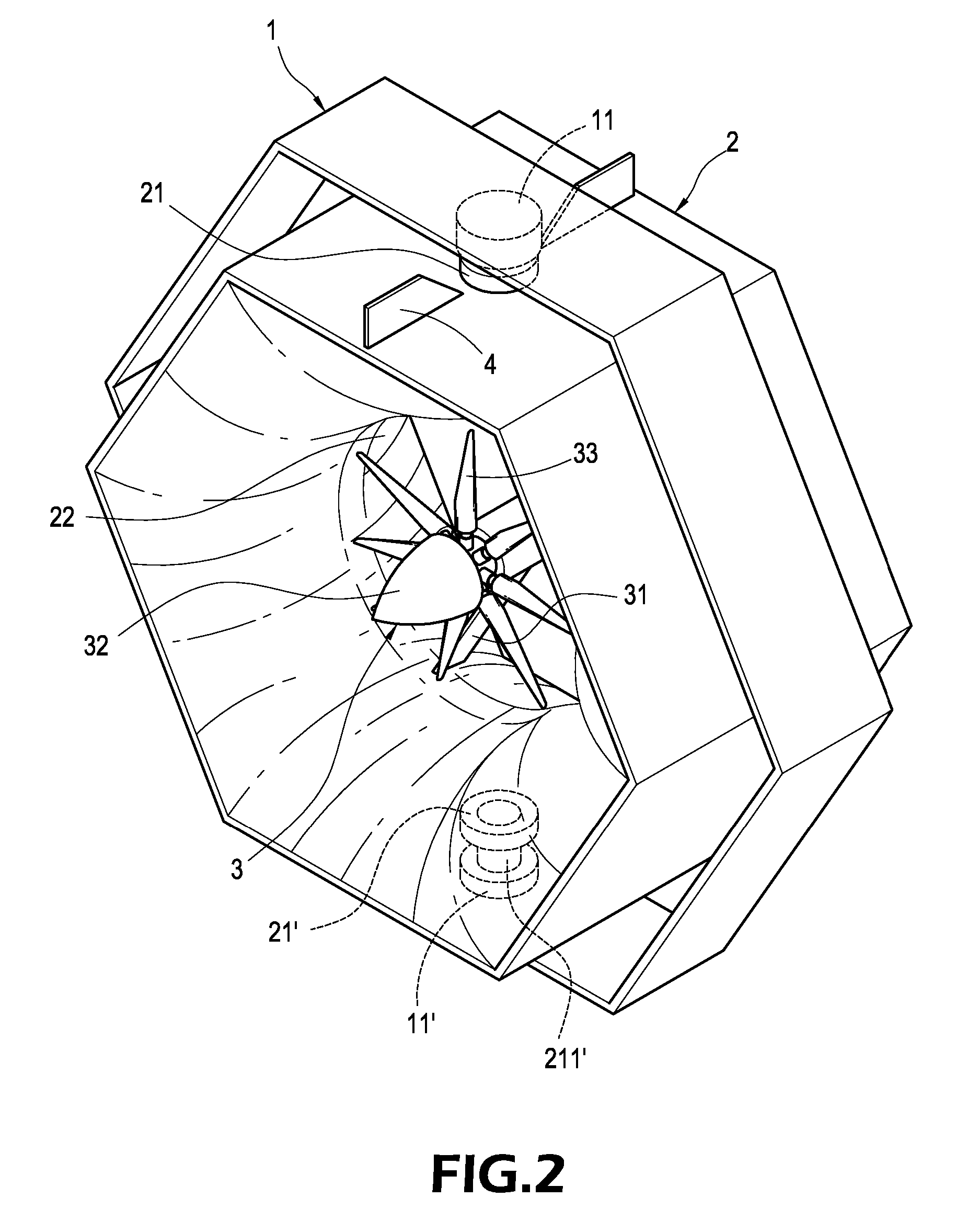
[0016] Referring to FIGS. 1 to 3 for the schematic views of the disassembled structure, the assembled structure and the cross-sectional view of the present invention, the improved wind guiding hood structure for wind power generation in accordance with the invention comprises a frame 1, a wind guiding hood 2, a turbine 3 and a wind direction detector 4, wherein the wind surface of the wind guiding hood 2 can be turned and adjusted in the frame 1, so that the wind guiding hood 2 can obtain a larger wind load for the turbine 3 to generate electric power.

[0017] The frame 1 includes two corresponding joint portions 11, 11′, and the joint p...


PUM


Abstract

A wind guiding hood for wind power generation includes a frame, a wind guiding hood, a turbine and a wind direction detector. The turbine is installed in the wind guiding hood, and the wind guiding hood is pivotally connected into the frame. After the wind direction detector installed on the wind guiding hood detects a change in wind direction, a correct wind direction signal is transmitted to an actuator installed on the frame to drive the actuator to control the turning direction of the wind guiding hood and adjust the wind surface, so that the wind guiding hood can obtain a larger wind load for the turbine to generate electric power.

Description

BACKGROUND OF THE INVENTION [0001] 1. Field of the Invention [0002] The present invention relates to a wind power generator, and more particularly to a wind guiding hood capable of detecting a change in wind direction to adjust the wind surface, so as to obtain a larger wind load for a turbine to generate electric power. [0003] 2. Description of Prior Art [0004] A wind power generating apparatus as disclosed in R.O.C. Pat. No. M250048 and used for obtaining the wind energy from a wind flow and converting the wind energy into usable electric energy comprises: a base; a frame erected from the base; a plurality of partitions installed in the frame to define a plurality of wind collecting partitions arranged in a grid nested shape, and each wind collecting partition has a windward opening for allowing wind to flow inward and a leeward opening for wind to flow outward; a plurality of wind wheels installed in the wind collecting partitions respectively, and each wind wheel includes a hub ...

Claims


Application Information

Patent Timeline
Patent Type & Authority Applications(United States)
IPC IPC(8): F03B15/06F03D1/00F03D1/04F03D7/02
CPCF03D1/04F03D7/0204Y02E10/723F05B2240/40F05B2270/321F05B2240/133Y02E10/72F03D1/02F03D9/25
Inventor CHEN, SHIHH
Owner JETPRO TECH
Why Eureka
Try Eureka