Gas Turbine Energy Supplementing Systems and Heating Systems, and Methods of Making and Using the Same

a technology of energy supplementing system and gas turbine, which is applied in the direction of engine starter, turbine/propulsion engine ignition, machine/engine, etc., can solve the problems of limiting the level of turn down that can be practicably achieved, and affecting the efficiency of the plant. achieve the effect of increasing the capacity and regulation capability

Active Publication Date: 2015-08-20
POWERPHASE
View PDF2 Cites 29 Cited by
  • Summary
  • Abstract
  • Description
  • Claims
  • Application Information

AI Technical Summary

Benefits of technology

[0008]The current invention provides several options, depending on specific plant needs, to improve the upper limit of the power output of the gas turbine, thus increasing the capacity and regulation capability of a new or existing gas turbine system.

Problems solved by technology

Unfortunately, because industrial gas turbines, which represent the majority of installed base, were designed primarily for base load operation, when they are cycled, a severe penalty is associated with the maintenance cost of that particular unit.
That same cost could be incurred in one year for a plant that is forced to start up and shut down every day.
Maintaining safe compressor operation and emissions typically limit the level of turn down that can be practically achieved.
This has a further negative impact on the efficiency of the system as the work performed on the air that is bled off is lost.
Additionally, the combustion system also presents a limit to the system.
The combustion system usually limits the amount that the system can be turned down because as less fuel is added, the flame temperature reduces, increasing the amount of CO emissions that is produced.
As the gas turbine mass flow is turned down, the compressor and turbine efficiency falls off as well, causing an increase in heat rate of the machine.
Some operators are faced with this situation every day and as a result, as the load demand falls, gas turbine plants hit their lower operating limit and have to turn the machines off which cost them a tremendous maintenance cost penalty.
Thus, TCLA is a significant penalty to the performance of the gas turbine system.

Method used


Image

  • Gas Turbine Energy Supplementing Systems and Heating Systems, and Methods of Making and Using the Same
  • Gas Turbine Energy Supplementing Systems and Heating Systems, and Methods of Making and Using the Same
  • Gas Turbine Energy Supplementing Systems and Heating Systems, and Methods of Making and Using the Same

Examples


Embodiment Construction

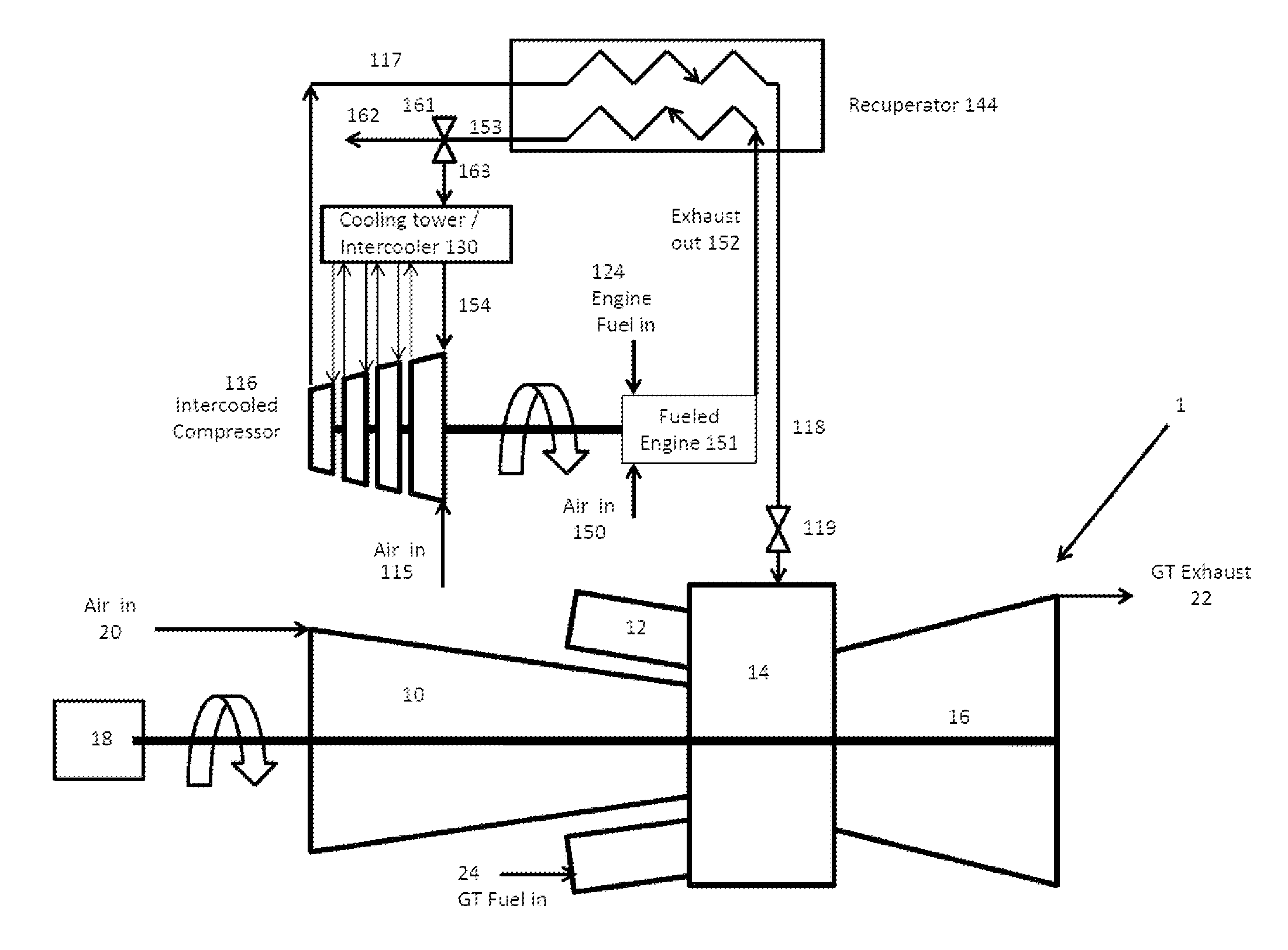
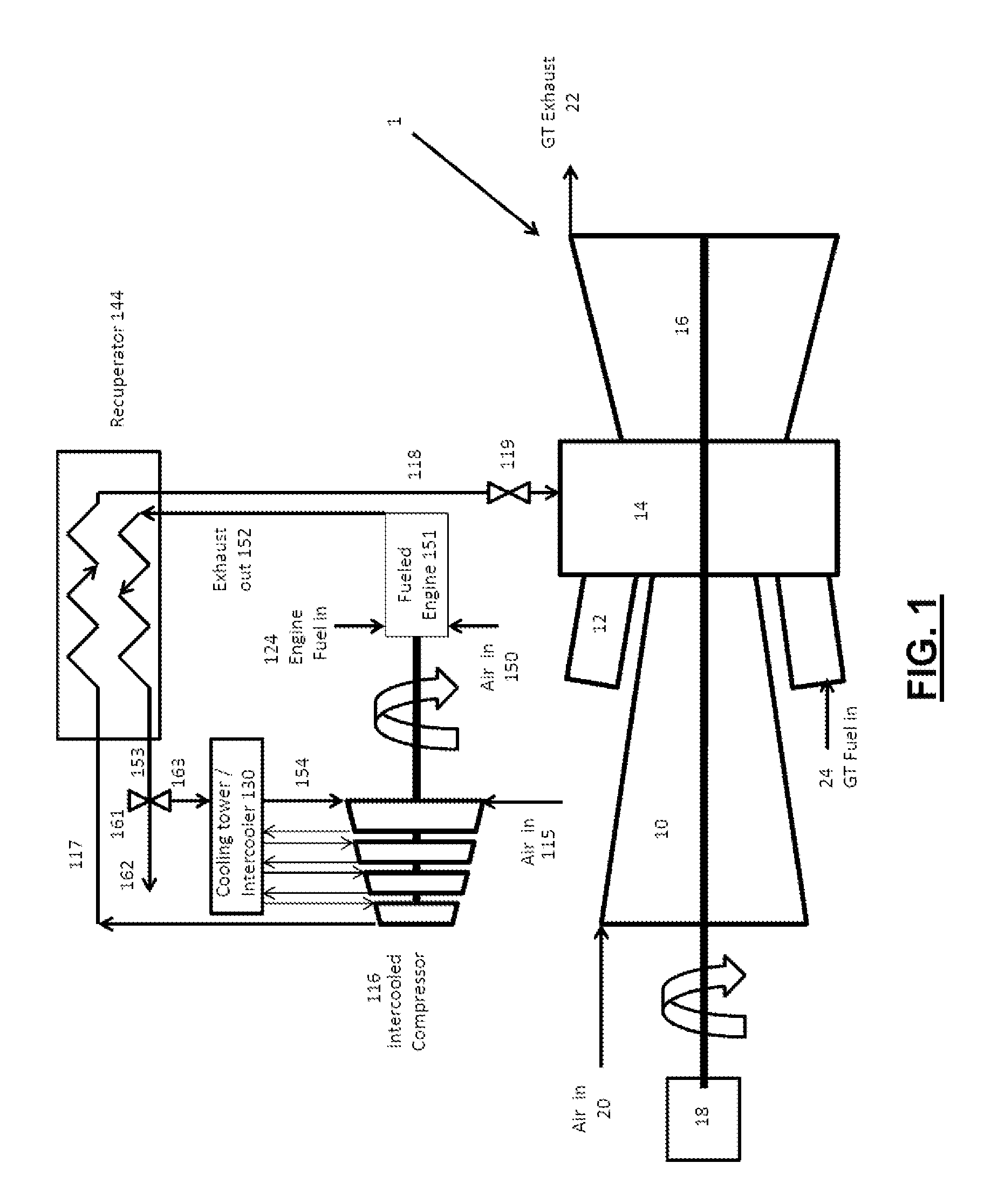
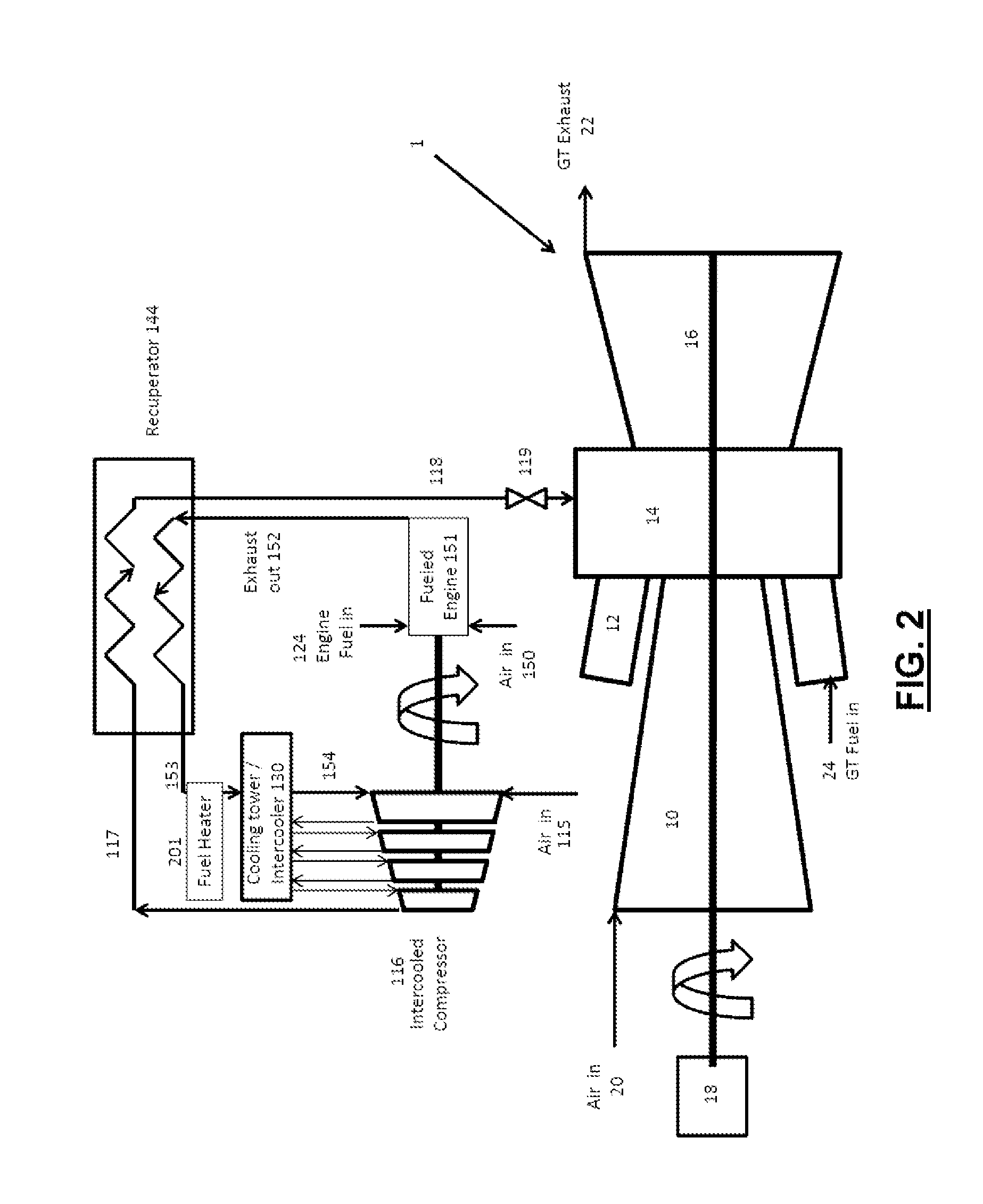
[0042]One aspect of the invention relates to methods and systems that allow gas turbine systems to run more efficiently under various conditions or modes of operation. In systems such as the one discussed in U.S. Pat. No. 6,305,158 to Nakhamkin (the “'158 patent”), there are three basic modes of operation defined, a normal mode, charging mode, and an air injection mode, but it is limited by the need for an electrical generator that has the capacity to deliver power “exceeding the full rated power” that the gas turbine system can deliver. The fact that this patent has been issued for more than 10 years and yet there are no known applications of it at a time of rapidly rising energy costs is proof that it does not address the market requirements.

[0043]First of all, it is very expensive to replace and upgrade the electrical generator so it can deliver power “exceeding the full rated power” that the gas turbine system can currently deliver.

[0044]Another drawback is that the system canno...


PUM


Abstract

Electrical power systems, including generating capacity of a gas turbine, where additional electrical power is generated utilizing a separately fueled system during periods of peak electrical power demand.

Description

FIELD OF THE INVENTION[0001]The invention relates generally to electrical power systems, including generating capacity of a gas turbine, and more specifically to energy storage that is useful for providing additional electrical power during periods of peak electrical power demand and providing systems that keep the gas turbine and steam turbine hot and ready to run thus reducing start up time.BACKGROUND OF THE INVENTION[0002]Currently marginal energy is produced mainly by gas turbine, either in simple cycle or combined cycle configurations. As a result of load demand profile, the gas turbine base systems are cycled up during periods of high demand and cycled down or turned off during periods of low demand. This cycling is typically driven by the Grid operator under a program called active grid control, or AGC. Unfortunately, because industrial gas turbines, which represent the majority of installed base, were designed primarily for base load operation, when they are cycled, a severe...

Claims


Application Information

Patent Timeline
Patent Type & Authority Applications(United States)
IPC IPC(8): F02C7/22
CPCF02C7/22F05D2270/331F02C9/50F02C9/52F05D2270/082F05D2270/06F05D2270/071Y02E20/16Y02E60/16F02C6/00F02C6/16
Inventor KRAFT, ROBERT J.
Owner POWERPHASE
Why Eureka
Try Eureka