Cover panel structure of a ball surface

a technology of ball surface and cover panel, which is applied in the direction of hollow balls, non-inflatable balls, sports equipment, etc., can solve the problems of economic and environmental protection of the conventional method of making balls, and achieve the effect of improving the surface structure and reducing the waste of materials

Inactive Publication Date: 2007-01-11
CHANG YEN LI
View PDF4 Cites 28 Cited by
  • Summary
  • Abstract
  • Description
  • Claims
  • Application Information

AI Technical Summary

Benefits of technology

[0007] The primary objective of the present invention is to provide an improved ba...

Problems solved by technology

Taking the cost and environment into consideration, the conventiona...

Method used


Image

  • Cover panel structure of a ball surface
  • Cover panel structure of a ball surface
  • Cover panel structure of a ball surface

Examples


Embodiment Construction

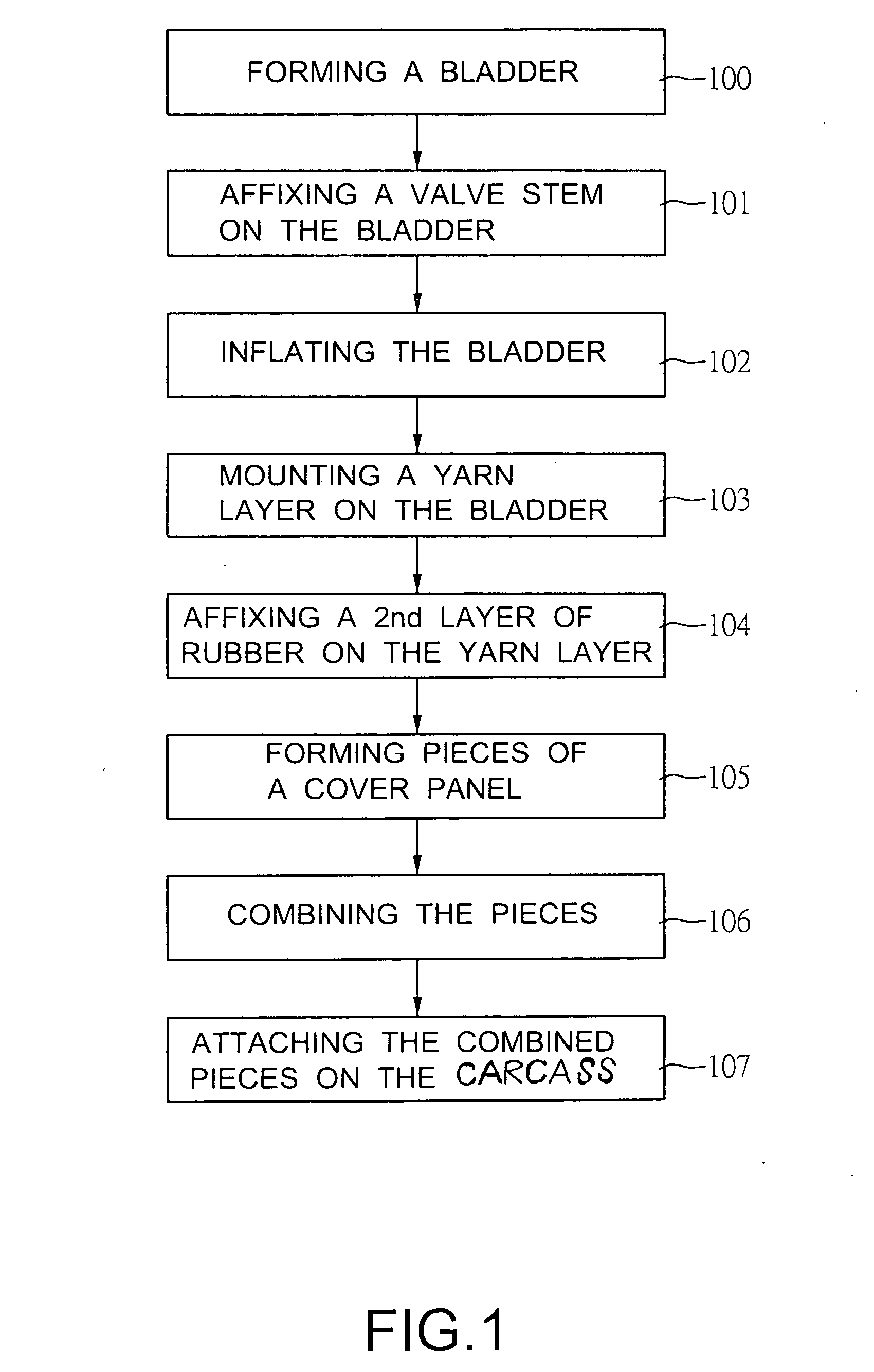
[0018] With reference to FIG. 1, it is noted that the process for making a ball in accordance with the present invention includes the steps of forming a bladder (100), affixing a valve stem on a surface of the bladder (101), inflating the bladder (102), mounting a yarn layer onto the bladder (103), affixing a second layer of rubber on the yarn layer (104) to form a carcass, forming pieces of a cover panel (105), combining the pieces of the cover panel (106) and attaching the combined cover panels onto the carcass (107).

[0019] After the cover panels are securely attached to the carcass, the ball is completed.

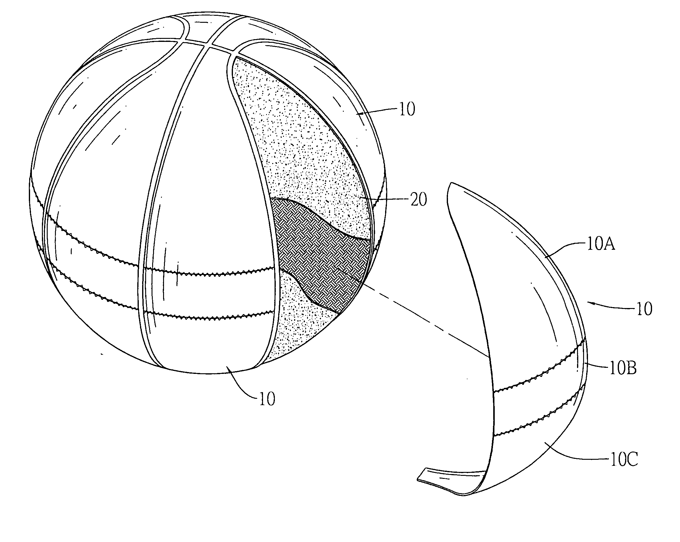
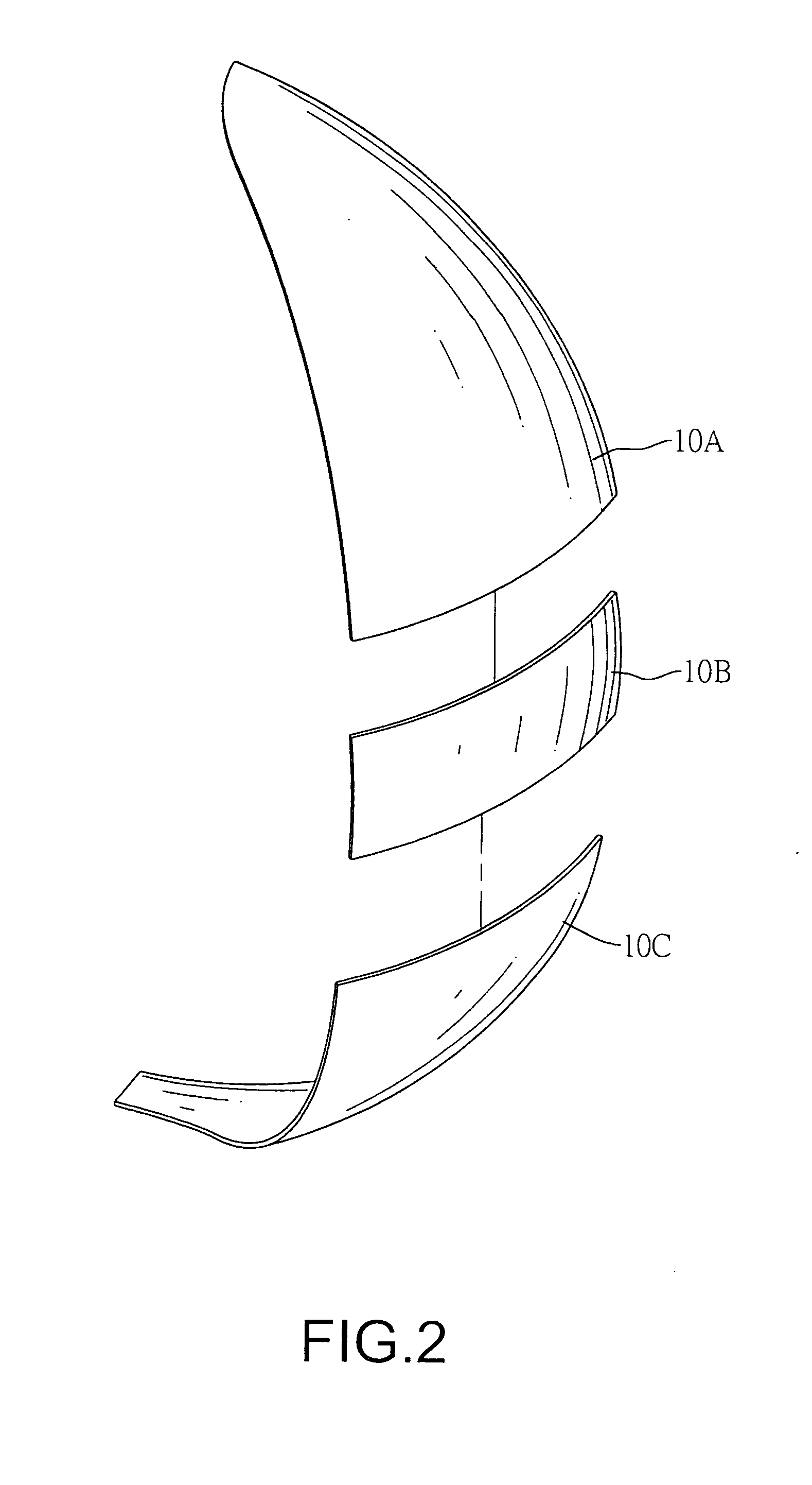
[0020] With reference to FIGS. 2, 3, and 4, it is noted that in order to accomplish the goal of reducing material waste, each of cover panels (10) forming a partial outer periphery of a ball is composed of secondary pieces of different shapes and dimensions, i.e. a top piece (10A), a mediate piece (10B) and a bottom piece (10C).

[0021] From this preferred embodiment of the pres...


PUM


Abstract

A cover panel structure for making a ball surface includes multiple secondary pieces of different shapes and dimensions to be combined together to form an oval shape.

Description

BACKGROUND OF THE INVENTION [0001] 1. Field of the Invention [0002] The present invention relates to a ball surface structure, and more particularly to a cover panel structure of a ball surface to reduce waste of material during manufacture of the ball. [0003] 2. Description of Related Art [0004] A conventional ball, as shown in FIGS. 6 and 7, generally comprises a spherical bladder having a carcass (80) which is a hollow rubber ball (not shown) affixed thereto. The carcass has a yarn layer (70) mounted thereon and a plurality of projection ribs (71) integrally protruded and extended on the carcass to define eight leaf shaped recesses surrounded by the ribs (71). Then eight cover panels (60) are securely and respectively attached to a bottom face defining the panel recess to complete the production of the ball. [0005] Before attaching the cover panels (60) to the carcass, the user has to cut the cover panel (60) from a material plate. Because each cover panel (60) has a length subst...

Claims


Application Information

Patent Timeline
IPC IPC(8): A63B37/12A63B39/06A63B41/08
CPCA63B37/12A63B41/08A63B39/06
Inventor CHANG, YEN-LI
Owner CHANG YEN LI
Why Eureka
Try Eureka