Steerable guide wire with torsionally stable tip
- Summary
- Abstract
- Description
- Claims
- Application Information
AI Technical Summary
Benefits of technology
Problems solved by technology
Method used
Image
Examples
Embodiment Construction
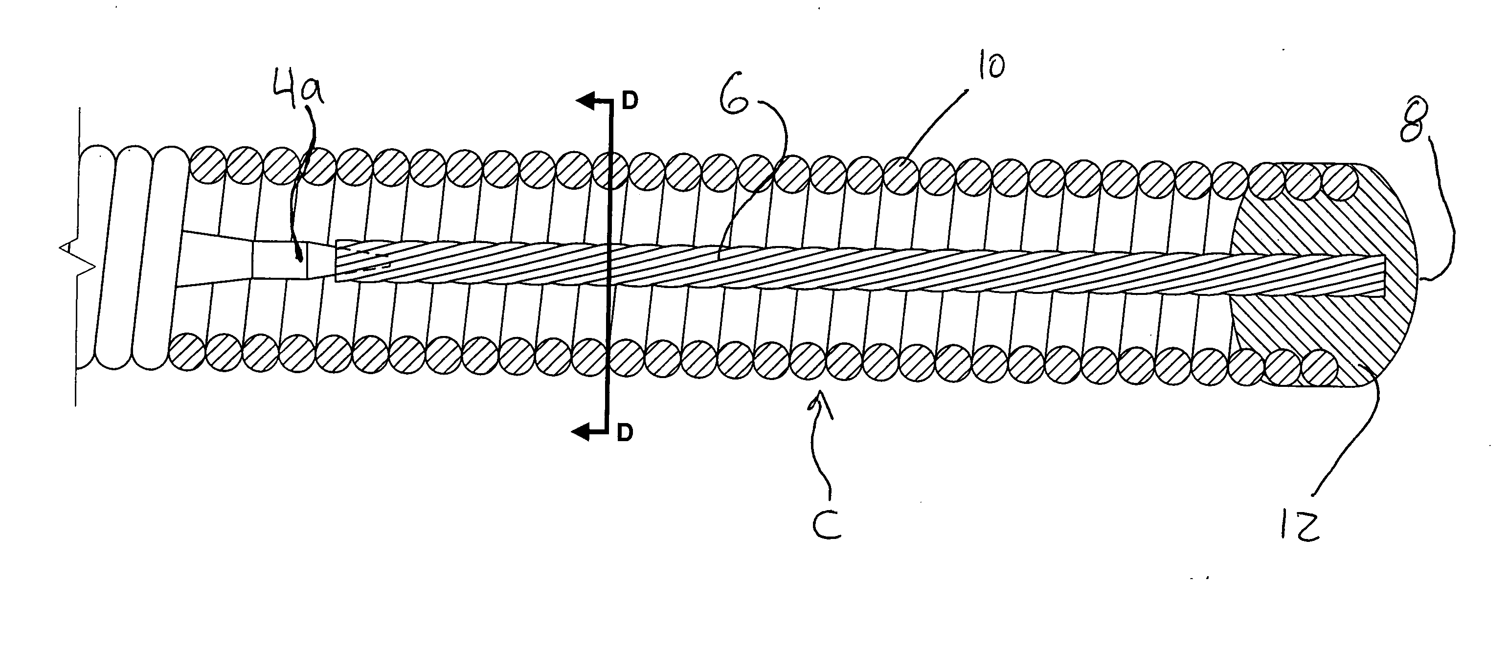
[0036]FIG. 3 illustrates a guide wire 2 according to one preferred aspect of the invention. The guide wire 2 generally includes a proximal portion A, a mid portion B, and a distal tip portion C. The guide wire 2 includes a solid core wire 4 that traverses the proximal and mid portions A, B and terminates in or near the distal tip portion C. As seen in FIG. 3, the diameter of the core wire 4 is reduced in the mid portion B of guide wire 2 to increase its flexibility. The distal end 4a of the core wire 4 is coupled to a multi-filament bundle 6. The multi-filament bundle 6 projects distally from the distal end 4a of the core wire 4 and terminates in a distal tip portion 8. The guide wire 2 further includes a coil 10 that is wrapped or wound around a portion of the exterior of the core wire 4 and multi-filament bundle 6. As seen in FIG. 3, the coil 10 begins in the mid portion B of the guide wire 2 and terminates at the distal tip 8. The distal tip 8 may include an end cap 12 such as a ...
PUM
 Abstract
Description
Claims
Application Information
 - R&D
- Intellectual Property
- Life Sciences
- Materials
- Tech Scout
- Unparalleled Data Quality
- Higher Quality Content
- 60% Fewer Hallucinations
Browse by: Latest US Patents, China's latest patents, Technical Efficacy Thesaurus, Application Domain, Technology Topic, Popular Technical Reports.
© 2025 PatSnap. All rights reserved.Legal|Privacy policy|Modern Slavery Act Transparency Statement|Sitemap|About US| Contact US: help@patsnap.com


