Optical microhand based on three-core optical fibre

A three-core optical fiber, single-core optical fiber technology, applied in the field of optical micro-hand, can solve the problems of complex three-dimensional optical waveguide preparation technology, large optical power loss, difficult interconnection, etc. Great capture effect

Inactive Publication Date: 2008-08-06
HARBIN ENG UNIV
View PDF2 Cites 39 Cited by
  • Summary
  • Abstract
  • Description
  • Claims
  • Application Information

AI Technical Summary

Problems solved by technology

For example, (1) the size of the optical waveguide is relatively large compared with that of the optical fiber; (2) the bending of the optical waveguide used will cause a large optical power loss; (3) the preparation technology of the three-dimensional optical waveguide is relatively complicated; ( 4) It is difficult and inconvenient to interconnect multiple optical fibers with optical waveguides

Method used


Image

  • Optical microhand based on three-core optical fibre
  • Optical microhand based on three-core optical fibre
  • Optical microhand based on three-core optical fibre

Examples


Embodiment Construction

[0031] The present invention is described in more detail below in conjunction with accompanying drawing example:

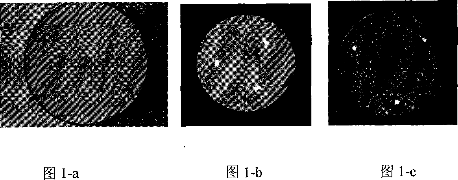
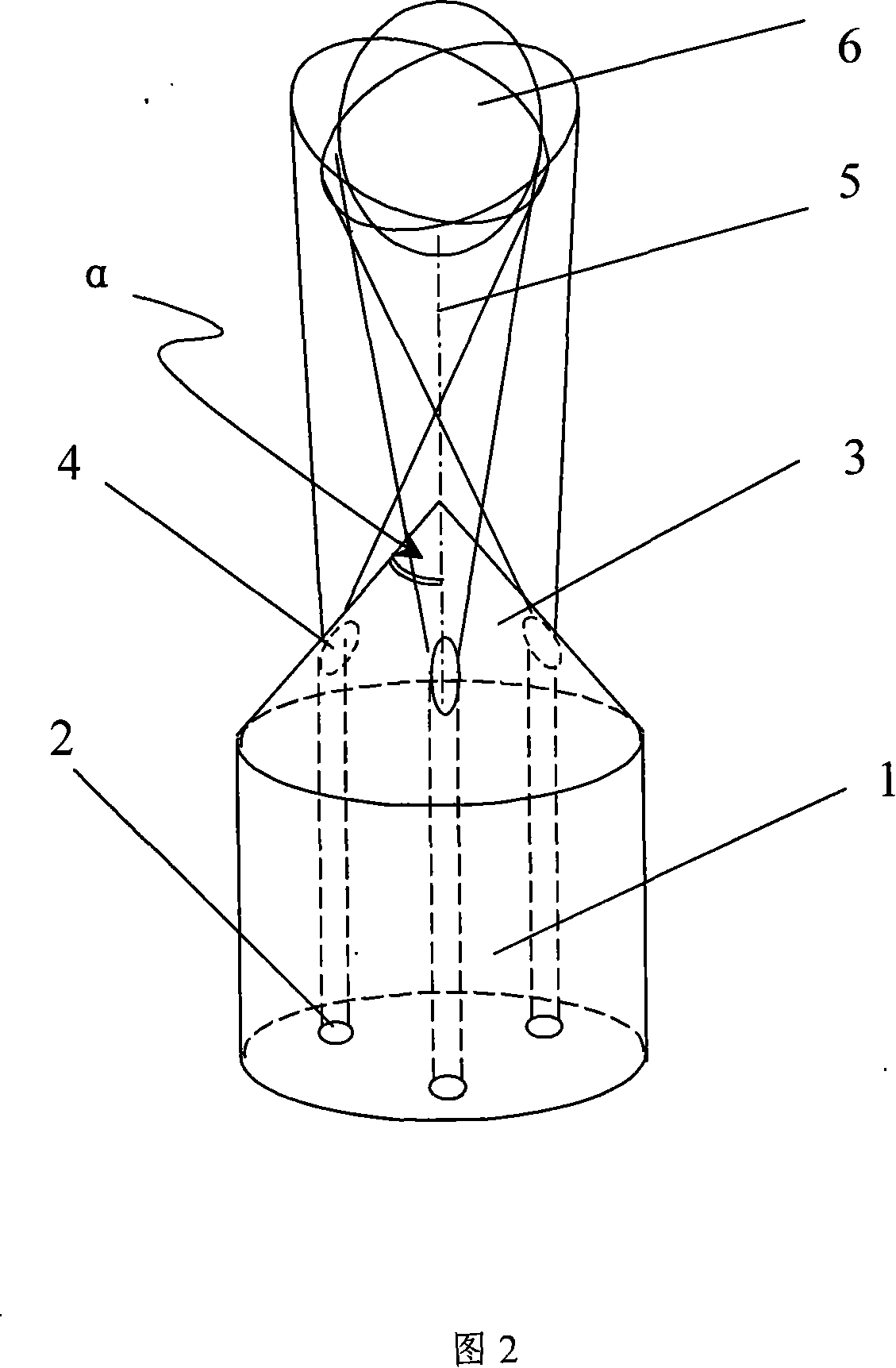
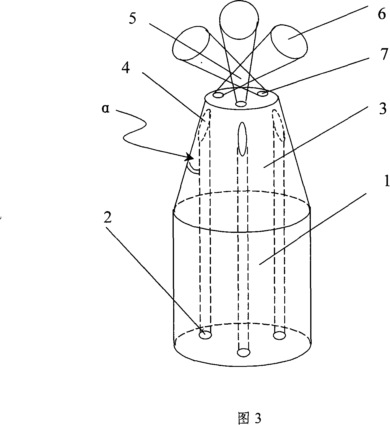
[0032] In conjunction with Fig. 2, the optical micro-hand of the first embodiment of the present invention includes an optical fiber, and the optical fiber includes a three-core optical fiber and a single-core optical fiber coupled and connected to the tail end of the three-core optical fiber, and the front end of the three-core optical fiber passes through the grinding of the optical fiber end It is made into a cone by the method of sintering at the tip after processing or heating to melt the taper. Among them: 1 is an optical fiber with a three-core structure; 2 is an optical fiber core in an equilateral triangle distribution state; 3 is an optical fiber end ground into a cone; 4 is an optical fiber core in an equilateral triangle distribution state exposed on the surface of the cone; 5 is the intersection area of ​​the three exiting light fields; 6 is the far f...


PUM

PropertyMeasurementUnit
refractive indexaaaaaaaaaa

Abstract

The invention provides an optical micro-hand based on a three-core fiber and a method for preparing the same. The fiber comprises a three-core fiber and a single-core fiber which is in coupled connection with the rear of the three-core fiber and the connection between the three-core fiber and the single-core fiber is realized by applying heating, fusing and tapering the welding point after welding. The other end of the three-core fiber is made into a cone by sintering at the sharp end after grinding or heating the ends of the fiber and applying fusing and tapering. Aiming at the defect and deficiency in the prior art, the optical micro-hand discloses an optical micro-hand based on a three-core fiber which can form a cross combination light field by grinding or tapering the ends of the fiber based on the three-core fiber by making use of the joint action among external refraction, internal reflection and external refraction as well as a cone gradual wave guide and further form a three dimensional gradient force potential trough at the convergence point of combination light fields so as to realize three dimensional trapping of tiny particles.

Description

(1) Technical field [0001] The invention relates to an optical microhand, in particular to an optical microhand based on a three-core optical fiber. (2) Background technology [0002] In 1986, Askin[A.Ashkin, J.M.Dziedzic, J.E.Bjorkholm, and S.Chu, Observation of a single-beam gradient force optical trap for dielectric particles, Opt.Lett.11, 288-290, 1986] introduced single-beam laser The high numerical aperture objective lens forms a three-dimensional optical potential well, which realizes the three-dimensional space control of the particles. A strong focused laser is used to simultaneously form a gradient force potential well in the x-y plane and along the z-axis direction, thereby stably trapping particles. Since the optical trap is formed using only one laser beam, it is called a single-beam gradient force optical trap, which is commonly referred to as optical tweezers. [0003] At present, people can use optical tweezers to capture, sort, manipulate and bend the cyto...

Claims


Application Information

Patent Timeline
Patent Type & Authority Applications(China)
IPC IPC(8): G02B6/036G02B6/255G01N15/00G01N37/00G21K1/00
Inventor 苑立波刘志海杨军张羽
Owner HARBIN ENG UNIV
Why Eureka
Try Eureka