Guidewire assembly including a repeatably inflatable occlusive balloon on a guidewire ensheathed with a spiral coil

a technology of spiral coil and guidewire, which is applied in the direction of guide wires, catheters, surgery, etc., can solve the problems of permanent damage of affected regions and similar damage to many other vessels in the body, such as peripheral vessels, cerebral vessels, etc., and achieve good steering

Inactive Publication Date: 2005-08-18
MEDRAD INC.
View PDF55 Cites 40 Cited by
  • Summary
  • Abstract
  • Description
  • Claims
  • Application Information

AI Technical Summary

Benefits of technology

[0018] This invention is directed to a guidewire assembly which can be utilized as an alternative to those guidewire assemblies disclosed in the three co-pending applications mentioned in the immediately preceding paragraph as well as that guidewire assembly disclosed in the aforementioned application filed on even date herewith. The guidewire assembly disclosed herein involves a repeatably inflatable occlusive device in the form of an occlusive balloon mounted on a guidewire ensheathed with a spiral coil. The ensheathed guidewire has an outer diameter ranging from 0.030 inch to 0.040 inch, preferably 0.035 inch, thus making it more robust than the guidewires of the above-mentioned applications such that it is strong enough to support the various surgical procedure devices that it is desired to employ with it. The spiral coil provides the guidewire with good steerability.
[0019] One significant aspect and feature of the present invention is a guidewire assembly which is able to adequately support surgical devices to be passed thereover and yet still be easily maneuverable.

Problems solved by technology

Ischemia refers to a substantial reduction or loss of blood flow to the heart muscle or any other tissue that is being supplied by the artery and can lead to permanent damage of the affected region.
While arterial disease is most commonly associated with the formation of hard plaque and coronary artery disease in the heart, similar damage can happen to many other vessels in the body, such as the peripheral vessels, cerebral vessels, due to the buildup of hard plaque or softer thrombus or grumous material within the lumen of an artery or vein.
The prior art guidewires suffer from several drawbacks.
One drawback is that the size is often too small to give enough support to larger peripheral devices that need to be passed thereover.
For example, the majority of guidewires used in the aforementioned interventional procedures have a maximum diametric dimension of 0.014 inch, and such is not sufficient to lend proper support to certain devices that need to be passed thereover.
Larger guidewires are known, e.g., guidewires having a diametric dimension as large as 0.035 inch, but those guidewires have poor steerability.
Also, prior art guidewires of this size have not been known to have an occlusive device, in particular an occlusive balloon, thereon.
Unfortunately, the standard interventional vascular treatments for debulking are only moderately successful when employed to treat saphenous vein coronary bypass grafts.
Atherectomy methods including directional, rotational, and laser devices are also associated with a high degree of embolization resulting in a greater likelihood of infarction.
Stents provide for less restenosis, but they do not eliminate the risk of embolization and infarction incurred by standard balloon angioplasty.
Except in the case of the normal cerebral anatomy where there are redundant arteries supplying blood to the same tissue, one of the problems with using an occlusive device in the arteries is that tissue downstream of the occlusive device can be damaged due to the lack of blood flow.
Consequently, an occlusive device that completely blocks the artery can only be deployed for a relatively short period of time.
The filter arrangements also are mechanically and operationally more complicated than an occlusive balloon device in terms of deployment and extraction.
While having numerous advantages, liquid fluids do not lend themselves to rapid deflation of an occlusive balloon because of the high resistance to movement of the liquid in a long small diameter tube.
In the context of a guidewire, however, liquid filled occlusive balloons typically cannot be deflated in less than a minute and, depending upon the length of the guidewire, can take up to several minutes to deflate.
Consequently, it is not practical to shorten the period of total blockage of a vessel by repeatedly deflating and then re-inflating a liquid filled occlusive balloon at the end of a guidewire.
While effective for use as an intra-aortic occlusive device, these occlusive devices are not designed for use as a guidewire as there is no ability to track a catheter over the intra-aortic occlusive device.
Although the use of occlusive devices has become more common for distal embolization protection in vascular procedures, particularly for treating a blocked saphenous vein coronary bypass graft, all of the existing approaches have significant drawbacks that can limit their effectiveness.
Liquid filled occlusive balloons can remain in place too long and take too long to deflate, increasing the risk of damages downstream of the occlusion.
Occlusive filters are designed to address this problem, but suffer from blockage problems and can be complicated to deploy and retrieve and may allow small embolic particles to migrate downstream.
Existing gas-filled occlusive balloons solve some of the problems of liquid filled occlusive balloons, but typically have utilized complicated valve and connection arrangements.

Method used


Image

  • Guidewire assembly including a repeatably inflatable occlusive balloon on a guidewire ensheathed with a spiral coil
  • Guidewire assembly including a repeatably inflatable occlusive balloon on a guidewire ensheathed with a spiral coil
  • Guidewire assembly including a repeatably inflatable occlusive balloon on a guidewire ensheathed with a spiral coil

Examples


Embodiment Construction

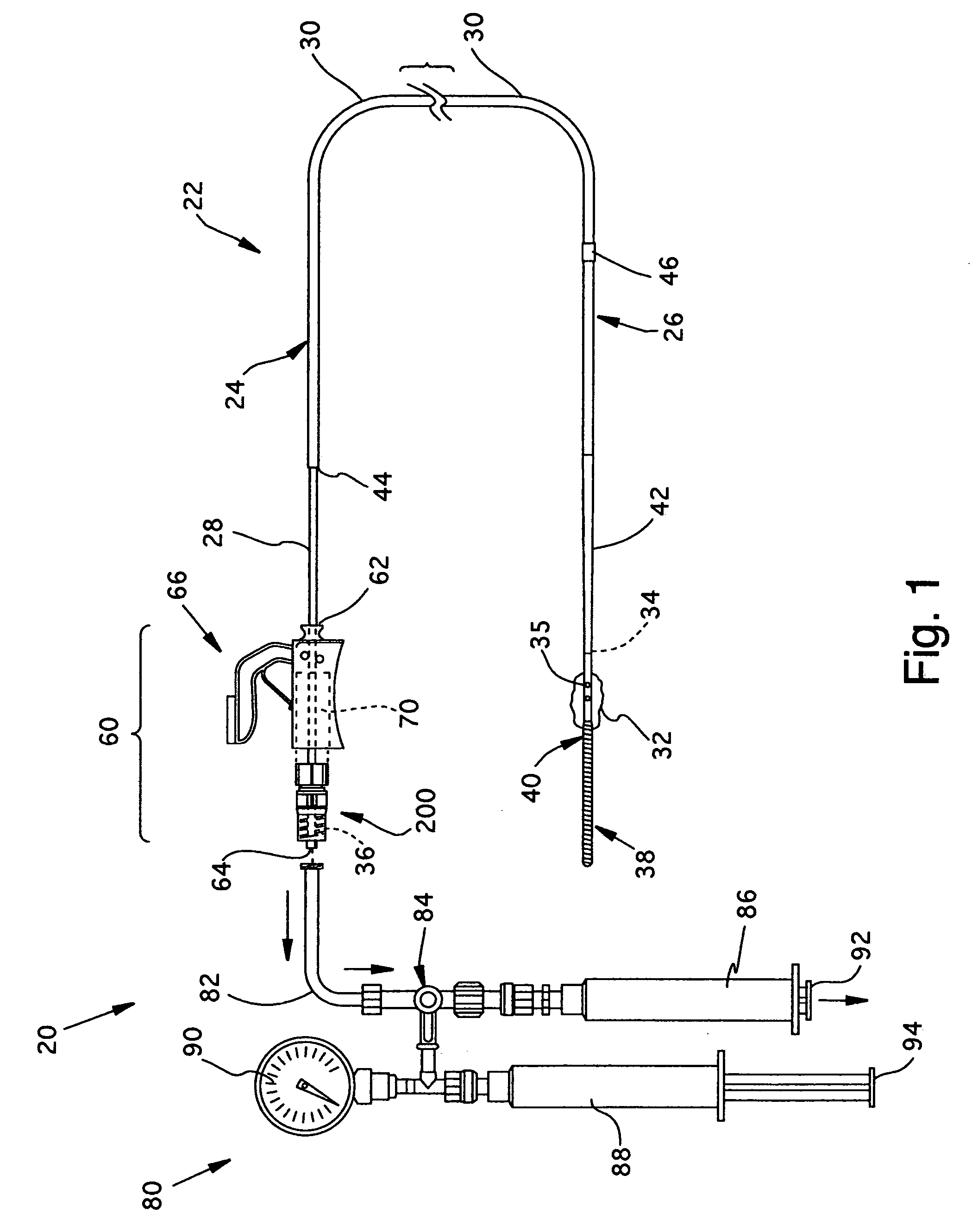
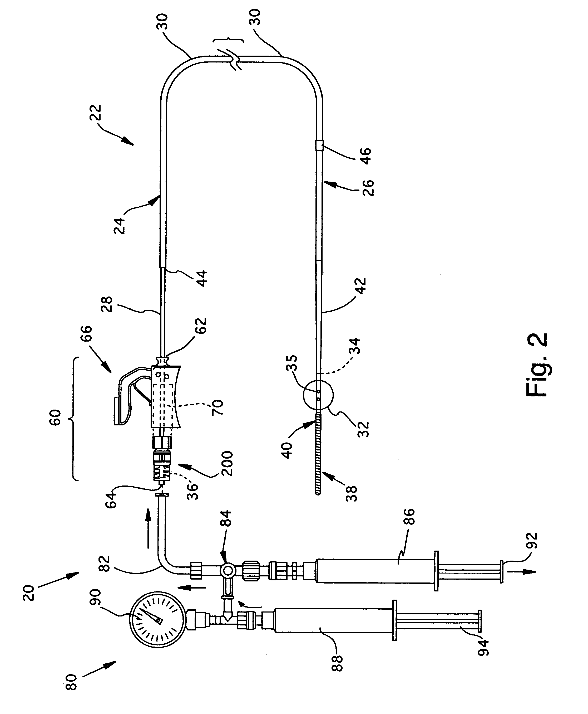
[0031] Referring now to FIGS. 1 and 2, the overall structure and operation of a guidewire occlusion system 20 will be described. The guidewire occlusion system 20 includes a guidewire assembly 22, a sealing system 60, and a gas inflation / evacuation system 80. The preferred embodiments of the overall guidewire occlusion system 20 are described in further detail in the previously identified co-pending applications entitled “Guidewire Occlusion System Utilizing Repeatably Inflatable Gas-Filled Occlusive Device”, “Guidewire Assembly Having Occlusive Device and Repeatably Crimpable Proximal End,”, and “Gas Inflation / Evacuation System and Sealing system for Guidewire Assembly Having Occlusive Device”.

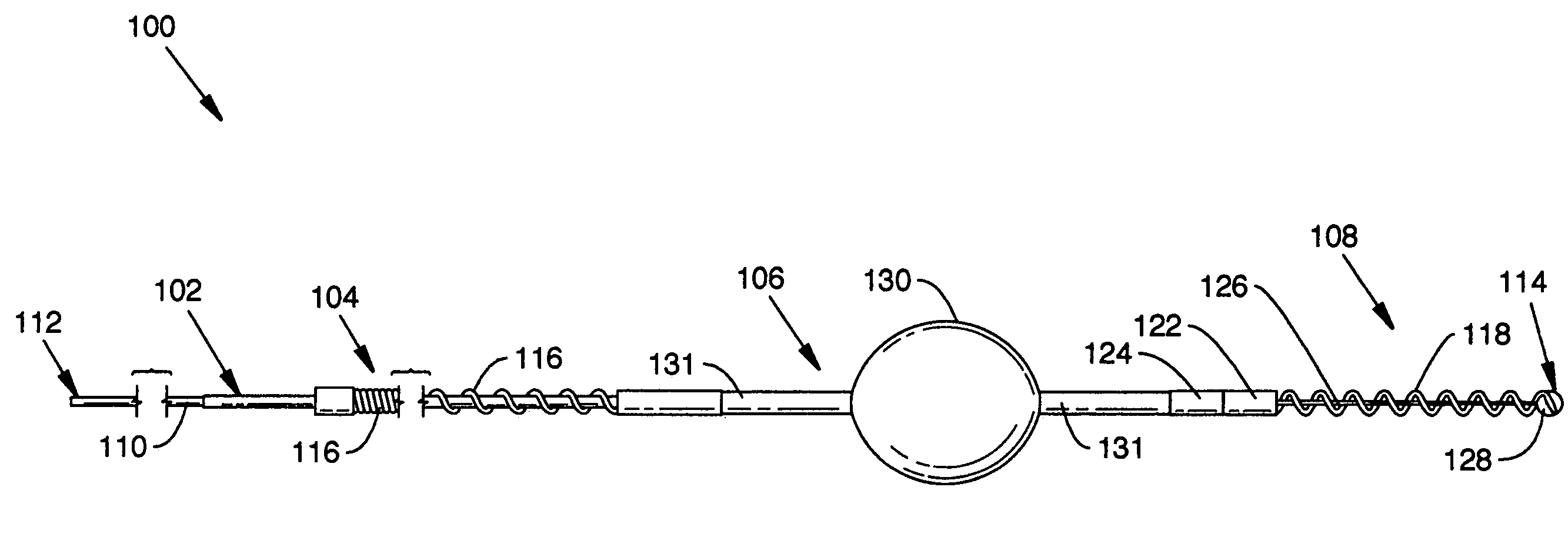
[0032] Guidewire assembly 22 includes a guidewire 24, an occlusive device such as an occlusive balloon 32, and, optionally, a flexible tip 38. The guidewire 24 is tubular and comprises an extended sealable section 28, a main body portion 30, and a distal portion 26. Extended sealable section...


PUM


Abstract

A guidewire assembly including a repeatably inflatable occlusive balloon on a guidewire ensheathed in a close wound spiral coil. The guidewire assembly is used as part of a guidewire occlusion system.

Description

CROSS REFERENCES TO RELATED APPLICATIONS [0001] This application is a continuation-in-part of U.S. patent application Ser. No. 10 / 012,903, filed Nov. 6, 2001, entitled “Guidewire Occlusion System Utilizing Repeatably Inflatable Gas-Filled Occlusive Device,” and U.S. patent application Ser. No. 10 / 012,891, filed Nov. 6, 2001, entitled “Guidewire Assembly Having Occlusive Device and Repeatably Crimpable Proximal End,” and U.S. patent application Ser. No. 10 / 007,788, filed Nov. 6, 2001, entitled “Gas Inflation / Evacuation System and Sealing System for Guidewire Assembly Having Occlusive Device,” all of which are hereby incorporated herein by reference. [0002] Also related to the instant application is commonly owned patent application Ser. No. ______, entitled “Gas Inflation / Evacuation System and Sealing System Incorporating A Compression Sealing Mechanism for Guidewire Assembly Having Occlusive Device”, filed on even date herewith. This application too is hereby incorporated herein by ...

Claims


Application Information

Patent Timeline
Patent Type & Authority Applications(United States)
IPC IPC(8): A61F2/958A61M25/00A61M25/01A61M25/09A61M29/00
CPCA61M25/09A61M25/09033A61M2025/09083A61M2025/09008A61M25/1018A61M25/10187A61M25/10182
Inventor BONNETTE, MICHAEL J.THOR, ERIC J.PRATHER, RICHARD R.
Owner MEDRAD INC.
Why Eureka
Try Eureka