Medical guide wire
a technology of guide wires and wires, applied in the field of medical guide wires, can solve problems such as negative effects on steerability, and achieve the effects of smooth securement of good flexibility, good steerability, and improved rotation-following capability
- Summary
- Abstract
- Description
- Claims
- Application Information
AI Technical Summary
Benefits of technology
Problems solved by technology
Method used
Image
Examples
first embodiment
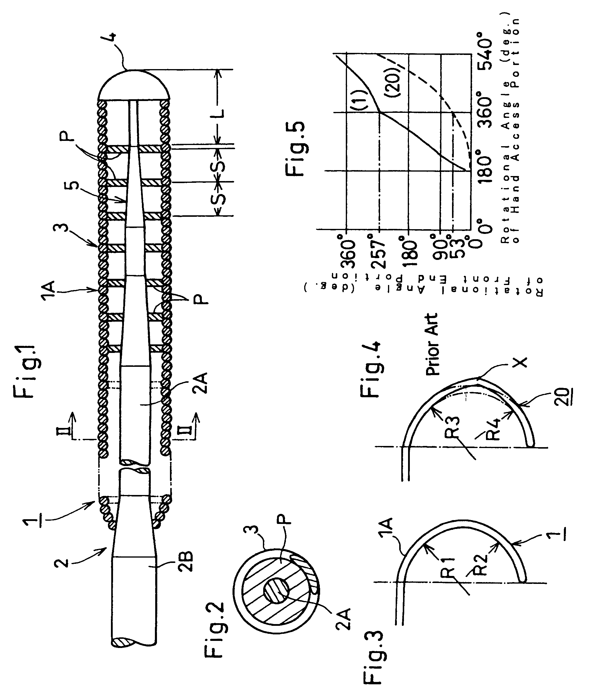
[0037]In the following description of the-depicted embodiments, the same reference numerals are used for features of the same type. Referring to FIGS. 1 through 5, a medical guide wire 1 (abbreviated as “guide wire 1” hereinafter) according to the invention is described below.
[0038]An entire length of the guide wire 1 is approximately 1500 mm, and a front end portion 1A of the guide wire 1 is approximately 300 mm. A front end 2A of a flexible elongation core member 2 is diametrically decreased successively in a fashion tapered-off from a hand access portion 2B (approx. 0.193 mm in diameter) to a leading end tip 4 (approx. 0.03 mm in diameter) so as to generally form a frustocone-shaped configuration 5. A helical spring 3 secured at both ends to the diameter-reduced front end portion 2A of the core member 2 has an outer diameter of 0.355 mm. A coil line (helice) of the helical spring 3 is 0.072 mm in diameter. The core member 2 and the helical spring 3 are made of a stainless steel m...
second embodiment
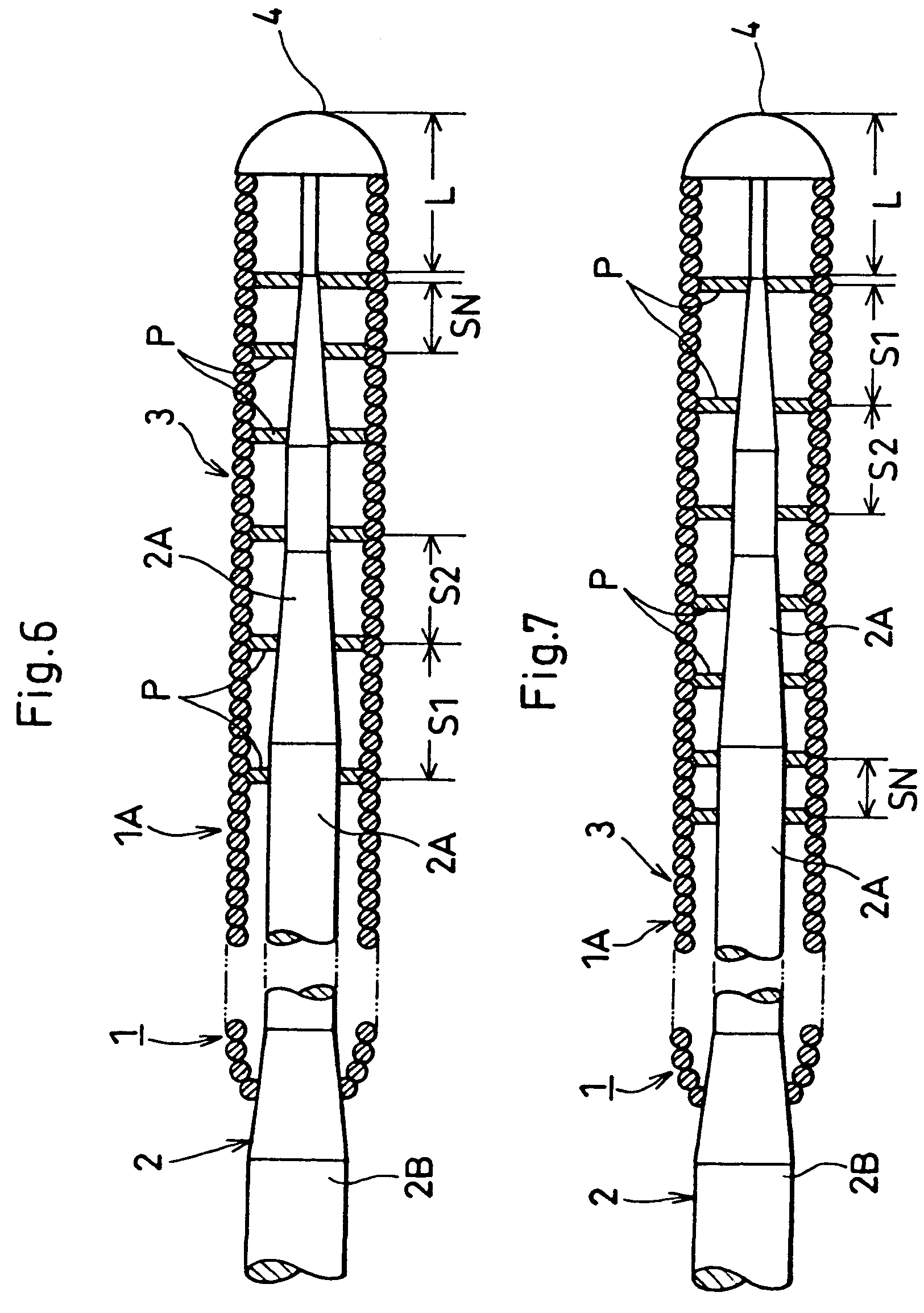
[0052]FIGS. 6 through 7 show the invention in which the securement points P are aligned at irregular spans S. The spans S decrease progressively in an arithmetic or geometric series as exemplified by S1, S2, . . . , SN from the hand access portion 2B to the leading end tip 4 as shown in FIG. 6. Alternatively, the spans S decrease progressively in the arithmetic or geometric series as exemplified by S1, S2, . . . , SN from the leading end tip 4 to the hand access portion 2B as shown in FIG. 7.
[0053]The adjustment of the spans S makes it possible to dimensionally determine the bending rigidity of the front end portion 1A of the guide wire 1 as desired. The magnitude of the bending rigidity determines the radius of curvature of the front end portion 1A bendable in each of the spans S. This enables the front end portion 1A to smoothly bend with the radius of curvature corresponding to the tortuous and meandering blood vessel (e.g., cardiovascular system) upon inserting the front end por...
third embodiment
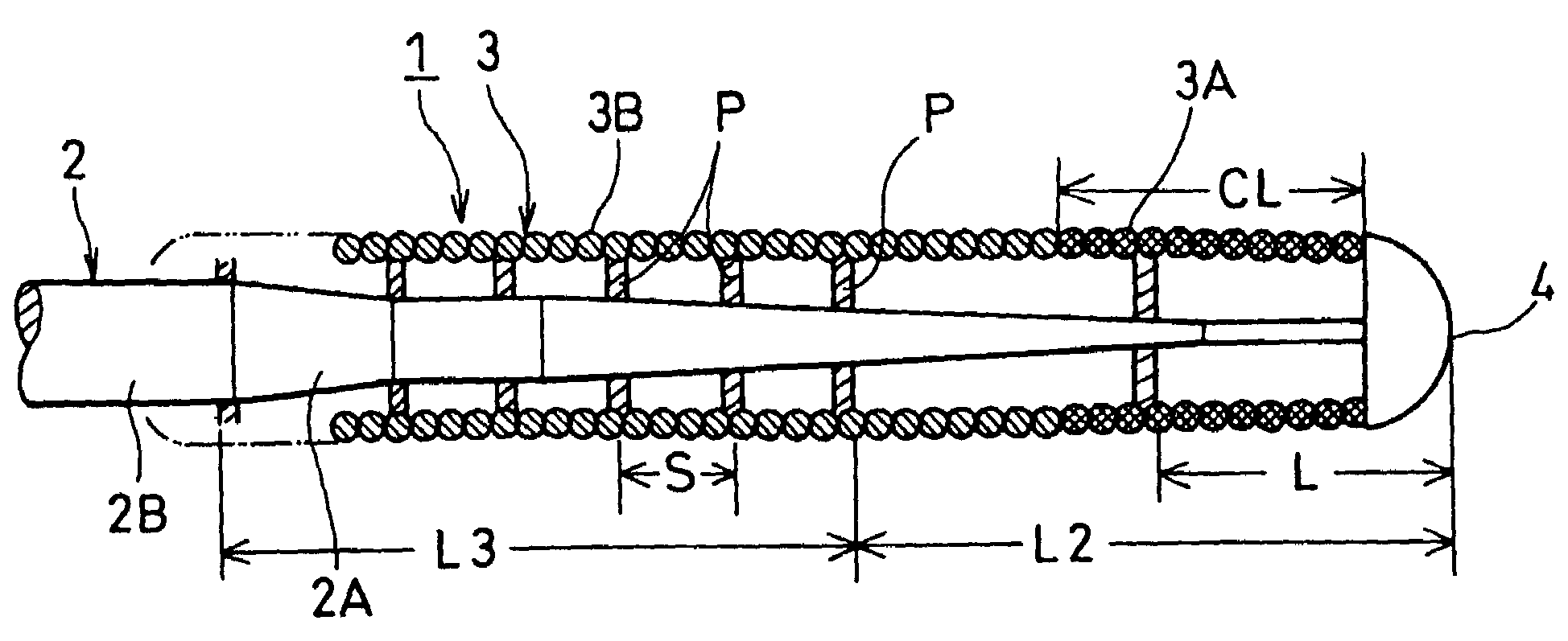
[0056]FIG. 8 shows the invention in which the helical spring 3 is made of two different metals. One is a platinum wire and the other a stainless steel wire. The platinum and stainless steel wires are connected in series by a welding procedure, and withdrawn to form a single raw wire until the coil line becomes 0.072 mm in diameter. The single raw wire is wound around a mandrel (not shown) to form a radiopaque helical configuration of different metals as a whole. Namely, the helical spring 3A is the radiopaque helical spring 3A and the radiotransparent helical spring 3B in turn located from a front end portion to a rear end portion of the helical spring 3 so as to provide a unitary helical configuration of different metals. An entire length (CL:30 mm) of the radiopaque helical spring 3A is an integral multiple of the span S (10 mm) formed by the securement points P aligned with the radiotransparent helical spring 3B at regular intervals.
[0057]In this instance, a breadth of the non-in...
PUM
 Abstract
Description
Claims
Application Information
 - R&D
- Intellectual Property
- Life Sciences
- Materials
- Tech Scout
- Unparalleled Data Quality
- Higher Quality Content
- 60% Fewer Hallucinations
Browse by: Latest US Patents, China's latest patents, Technical Efficacy Thesaurus, Application Domain, Technology Topic, Popular Technical Reports.
© 2025 PatSnap. All rights reserved.Legal|Privacy policy|Modern Slavery Act Transparency Statement|Sitemap|About US| Contact US: help@patsnap.com


