
Interrogation network patches for active monitoring of structural health conditions

a technology of active monitoring and diagnostic network, applied in the field of diagnostic network patch systems for monitoring structural health conditions, can solve the problems of inability to provide effective on-line methods to implement a reliable sensory network system, time-consuming and expensive, and inability to accommodate a large number of actuator arrays

Inactive Publication Date: 2007-01-18
ADVANCED STRUCTURE MONITORING
View PDF34 Cites 41 Cited by
  • Summary
  • Abstract
  • Description
  • Claims
  • Application Information

AI Technical Summary

Benefits of technology

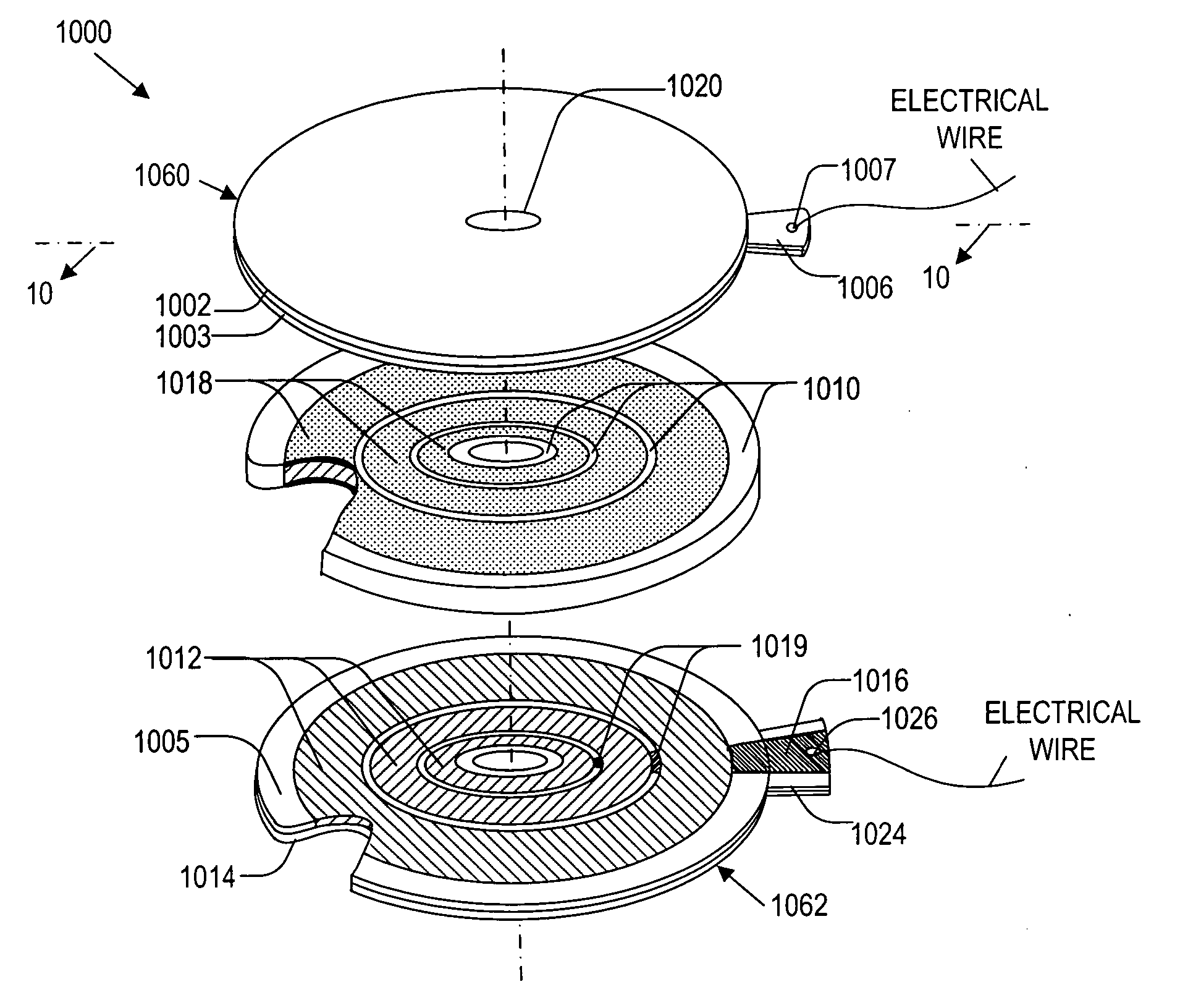
This patent describes devices used to monitor the structure of objects. One version of the device contains piezoelectric rings placed between insulating rings called fillers. Another version adds conductive materials above and below the piezoelectric rings. Both versions have upper and lower covers designed to keep everything in place. When voltage is applied to these devices, they produce vibrations which can be measured to assess the condition of the structures they're attached to. Overall, this technology allows for effective non-destructive testing of structures without causing damage.

Problems solved by technology

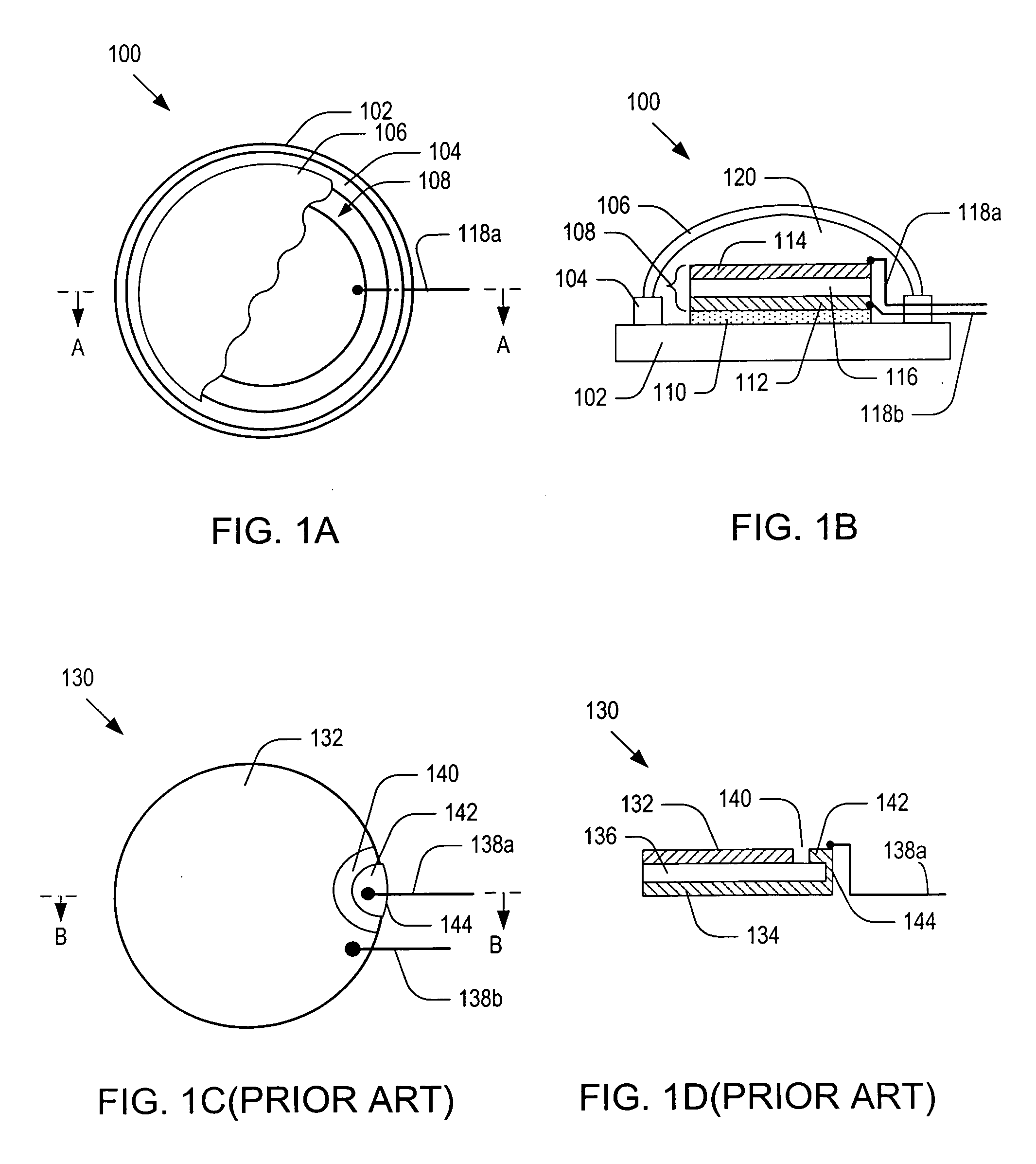
The technical problem addressed in this patent is the need for an efficient, accurate, and reliable system that can be readily integrated into existing and/or new structures and provide an on-line methodology to diagnose, classify, and forecast structural condition with the minimum intervention of human operators. Existing methods for detecting damage in structures have limitations, such as requiring temporary removal of structures for inspection and being unable to detect internal damages located between sensors. The present invention aims to overcome these limitations and provide a more effective and reliable solution for monitoring structural health.

Method used


Image

  • Interrogation network patches for active monitoring of structural health conditions
  • Interrogation network patches for active monitoring of structural health conditions
  • Interrogation network patches for active monitoring of structural health conditions

Examples


embodiment 180

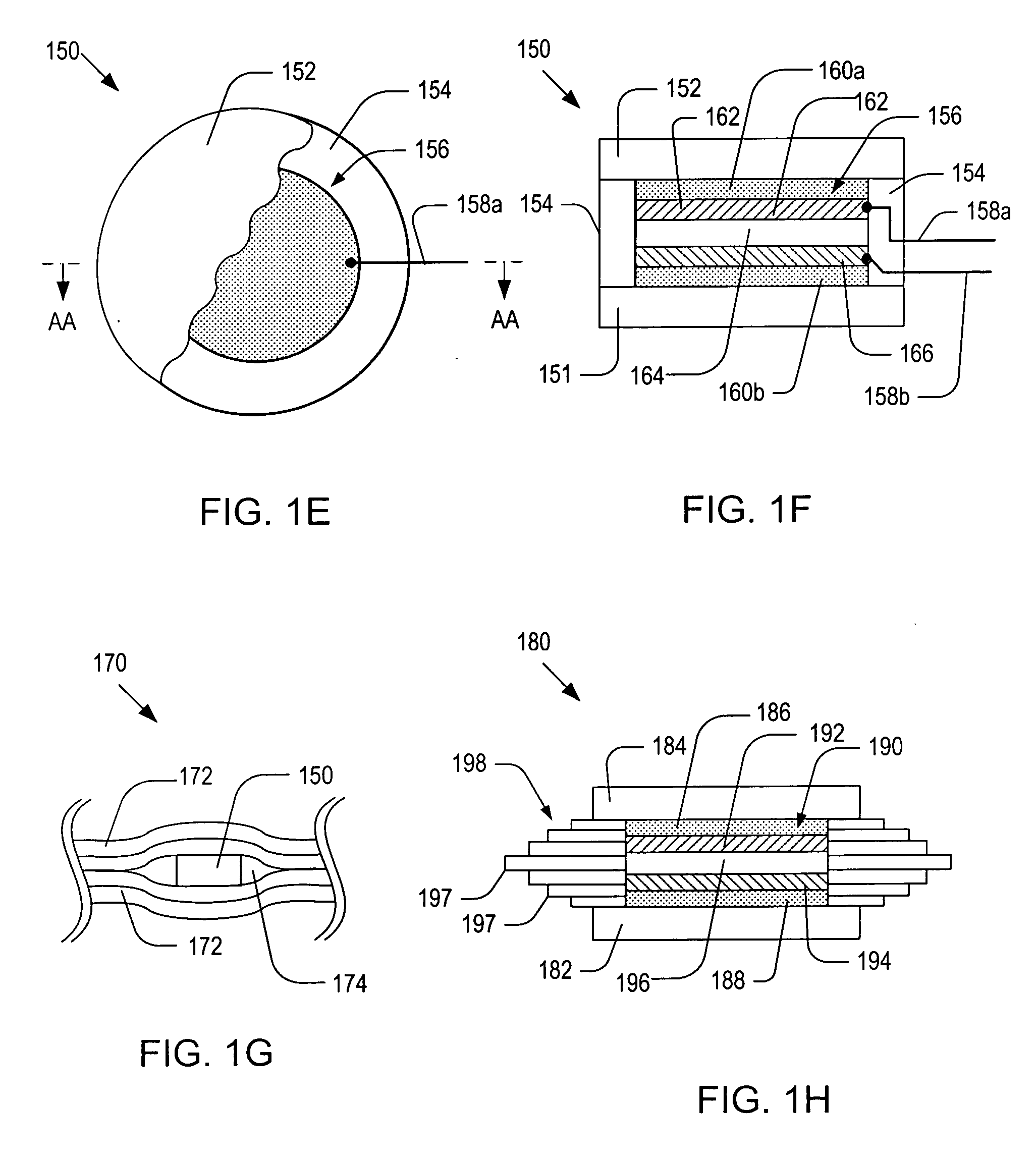
[0065]FIG. 1H is a schematic side cross-sectional view of an alternative embodiment 180 of the patch sensor 150 of FIG. 1E. As illustrated, the patch sensor 180 may include: a bottom substrate 182; a top substrate 184; a hoop layer 198; a piezoelectric device 190; top and bottom buffer layers 192 and 194; and the piezoelectric device 196. For simplicity, a pair of wires connected to the piezoelectric device 190 is not shown in FIG. 1H. The piezoelectric device 190 may include: a piezoelectric layer 196; a bottom conductive flake 194; and a top conductive flake 192. The functions and materials for the components of the patch sensor 180 may be similar to those of their counterparts of the patch sensor 150.

[0066] The hoop layer 198 may have one or more sublayers 197 of different dimensions so that the outer contour of the hoop layer 198 may match the geometry of cavity 174. By filling the cavity 174 with sublayers 197, the adhesive material may not be accumulated during the curing proc...

embodiment 318

[0078]FIG. 3C a schematic top cut-away view of the optical fiber coil 308 contained in the optical fiber patch sensor of FIG. 3A, illustrating a method for rolling the optical fiber cable 312. As shown in FIG. 3C, the outermost loop of the optical fiber coil 308 may start with one end 310a while the innermost loop may end with the other end 310b. FIG. 3D a schematic top cut-away view of an alternative embodiment 318 of the optical fiber coil 308 shown in FIG. 3C. As shown in FIG. 3D, the optical fiber cable 322 may be folded and rolled in such a manner that the outermost loops may start with both ends 320a-b. The rolled optical fiber cable 322 may be covered by a coating layer 319.

[0079] It is noted that the optical fiber coils 308 and 318 show in FIGS. 3C-D may be attached directly to a host structure and used as optical fiber coil sensors. For this reason, hereinafter, the terms “optical fiber coil” and “optical fiber coil sensor” will be used interchangeably. FIGS. 3E-F are alter...


PUM


Abstract

Apparatus for monitoring structural health conditions of structures. The apparatus includes a piezoelectric device that has a bottom cover plate, piezoelectric rings concentrically disposed with respect to an axis and positioned on the bottom cover plate, and concentric filler rings made from an electrically insulating material. Each of the piezoelectric rings is interposed between two adjacent filler rings. The piezoelectric device also includes electrical connection means for communicating electrical signals to the piezoelectric rings and a top cover plate that is positioned over the piezoelectric rings and filler rings. The electrical connection means are operative to transmit electrical signals that cause one or more of the piezoelectric rings to generate waves or transmit electrical signals developed by one or more of the piezoelectric rings in response to the waves.

Description


Claims


Application Information

Patent Timeline
Owner ADVANCED STRUCTURE MONITORING
Learn More