Interlock mechanism for lateral file cabinets

a technology for locking mechanisms and file cabinets, which is applied in the field of filing cabinets, can solve the problems of adding additional cost to the process of reconfiguring cabinets, difficult to change the configuration of drawers in cabinets, and difficult to reconfigure drawers in cabinets, etc., and achieves the effect of easy installation and resistance to high forces

Inactive Publication Date: 2007-01-18
KNAPE & VOGT MFG
View PDF3 Cites 28 Cited by
  • Summary
  • Abstract
  • Description
  • Claims
  • Application Information

AI Technical Summary

Benefits of technology

[0011] Accordingly, the present invention provides an interlock and lock that reduces the aforementioned difficulties, as well as other difficulties. The interlock and lock of the present invention allow relatively low-tensile strength cables or flexible members to be used in systems which provide high resistance to theft and breakdown. The system of the present invention further allows changes to cabinet configurations to be easily implemented with little or no additional work required to integrate the new cabinet configuration into the interlock or lock system. The present invention provides a simple construction for locks and interlocks that can be easily manufactured without excessively restrictive tolerances, and which can be easily installed in cabinets.
[0012] According to one aspect of the present invention, an interlock for a cabinet drawer is provided. The drawer is movable in the cabinet is a first direction toward an open position and in a second, opposite direction toward a closed position. The interlock includes an elongated, flexible member, a rotatable lever, an engagement member, and a biasing member. The lever is adapted to alter the amount of slack in the elongated, flexible member. The lever is rotatable between a first position and a second position. The first position creates a low amount of slack in the elongated, flexible member, and the second position allows a high amount of slack to be present in the elongated, flexible member. The engagement member is attached to the drawer and positioned to cause the rotatable lever to rotate toward the first position when the drawer is initially moved from the closed position in the first direction. The biasing member is positioned adjacent the lever and adapted exert a biasing force that tends to prevent the lever from rotating from the first position to the second position until the drawer is moved in the second direction to the closed position.
[0015] According to yet another aspect of the present invention, a cabinet is provided that includes at least one drawer movable within the cabinet in a first direction toward an open position and in a second, opposite direction toward a closed position. The cabinet further includes a frame adapted to support the drawer, an elongated, flexible member, an interlock, and a slack take up mechanism. The elongated, flexible member is positioned within the cabinet and changeable between a lower slack condition and a higher slack condition. The interlock is positioned within the frame and in operative engagement with the elongated, flexible member. The interlock is adapted to prevent the drawer from moving to the open position when the elongated, flexible member is in the lower slack condition and to allow the drawer to move to the open position when the elongated, flexible member is in the higher slack condition. The slack take up mechanism is adapted to change the elongated, flexible member from the higher slack condition to the lower slack condition when the drawer is moved from the closed position to the open position. The slack take up mechanism is further adapted to translate a first force exerted on the drawer in the first direction to a second force exerted on the elongated, flexible member which is less than the first force.

Problems solved by technology

One disadvantage is the difficulty of changing the drawer configurations within a cabinet.
In the past, such reconfiguring of the drawers in a cabinet has been a difficult task because the interlocking and / or locking system for the drawers could not easily be adjusted to match the newly configured filing cabinet.
Not only does this add additional cost to the process of reconfiguring the cabinet, it complicates the reconfiguring process by requiring new parts of precise dimensions to be ordered.
Finding these precisely dimensioned parts may involve extensive searching and / or measuring, especially where the manufacturer of the rods is not the same entity that produced the new drawers being installed, or the manufacturer of the rods has ceased producing the parts, or has gone out of business.
Another difficulty with systems like that disclosed in the Sawatzky patent is the precise manufacturing that may be required to create these rigid rods.
These interlock systems only work if the rods have heights that fall within a certain tolerance range.
These tight tolerances tend to increase the cost of the manufacturing process.
Another difficulty with past interlock and lock systems for file cabinets has been the expense involved in creating a locking system that will withstand high forces exerted on the drawers.
Thus, if a file cabinet does not exceed this standard, thieves can gain access to the contents of a lock drawer by pulling the drawer outwardly with more than fifty pounds of force.
Increasing the durability of the locking system often adds undesired expense to the cost of building the system.
Such systems, however, have suffered from other disadvantages.
Both systems suffer from the fact that excessive amounts of force may be easily transferred to either the cable or the strap.

Method used


Image

  • Interlock mechanism for lateral file cabinets
  • Interlock mechanism for lateral file cabinets
  • Interlock mechanism for lateral file cabinets

Examples


Embodiment Construction

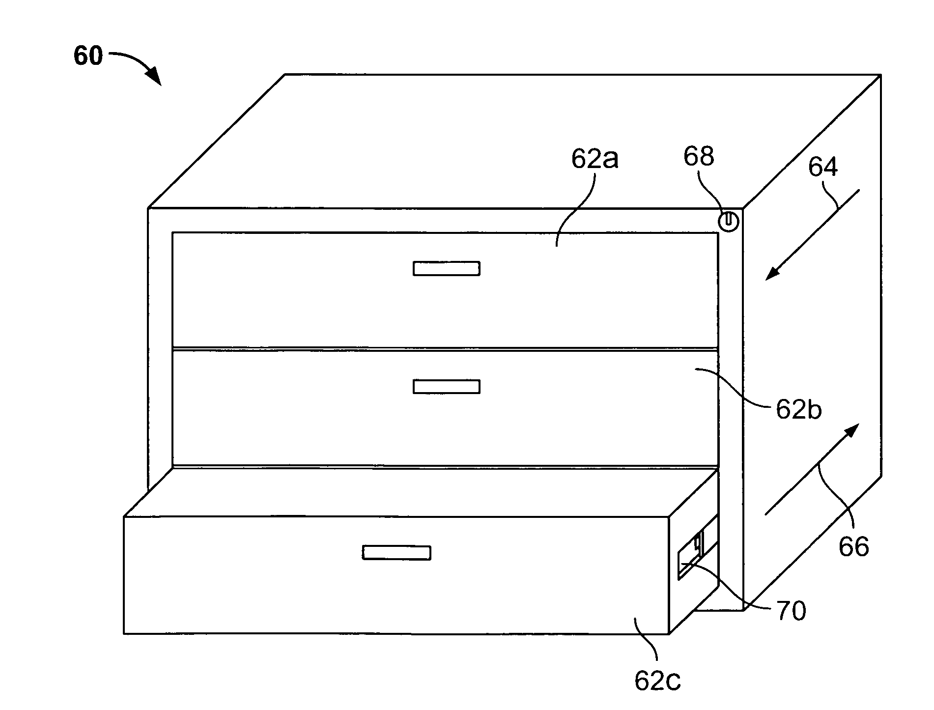
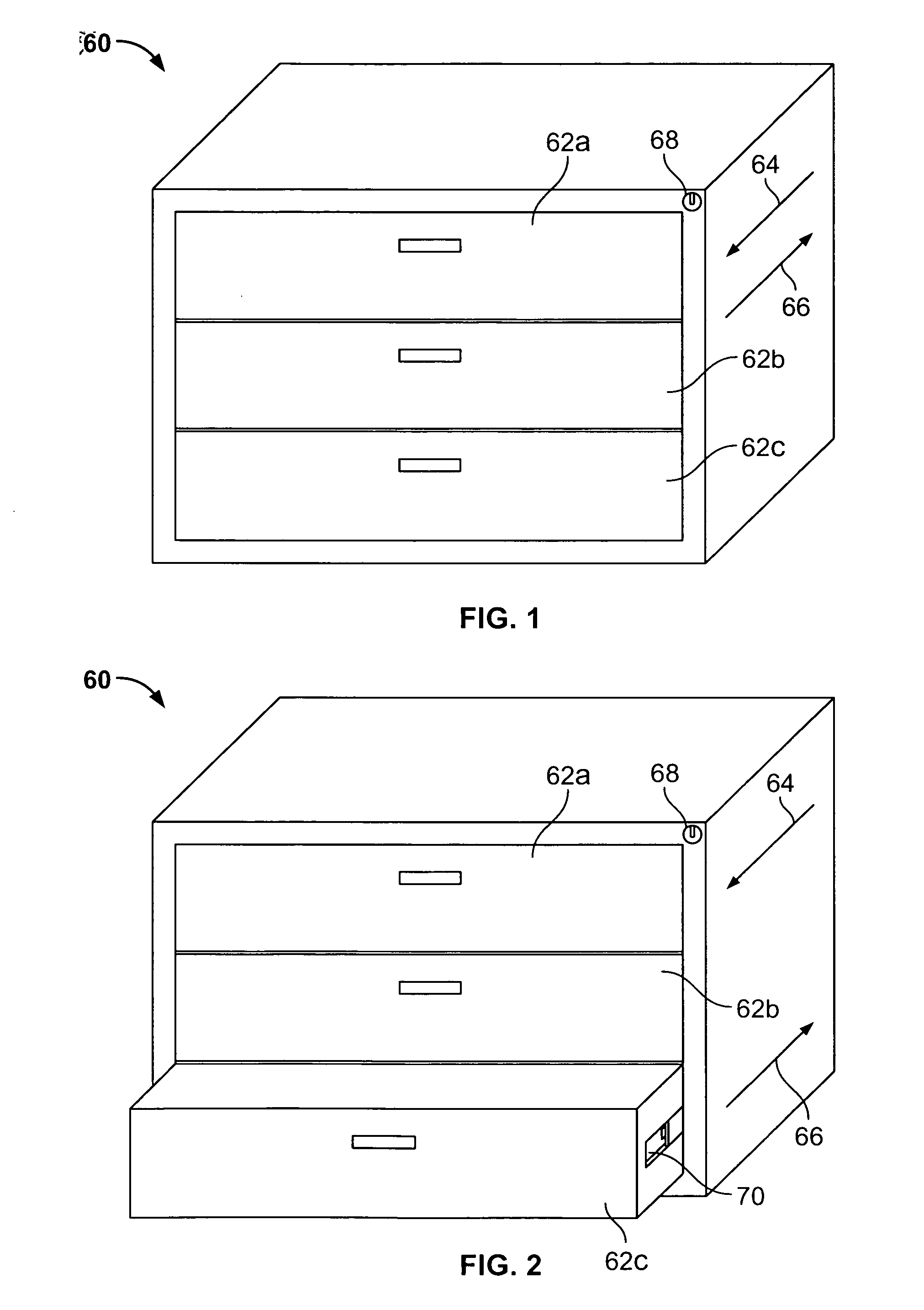
[0049] The present invention will now be described with reference to the accompanying drawings wherein the reference numerals in the following written description correspond to like numbered elements in the several drawings. The present invention relates to locks and interlocks that may be used with file cabinets, such as the file cabinet 60 depicted in FIGS. 1 and 2. File cabinet 60 includes three drawers 62a-c that are essentially stacked on top of each other in file cabinet 60. Each drawer can be pulled in a first direction 64 toward an open position. The lower most drawer 62c in FIG. 2 is illustrated in the open position. When it is time to close this drawer, it can be pushed in a second direction 66 back to its closed position. The interlocking system of the present invention prevents more than one drawer from being opened at a single time. While only three drawers are illustrated in file cabinet 60, the present invention is applicable to cabinets having any number of drawers. ...


PUM


Abstract

The invention relates to interlocks for file cabinets and the like which generally prevent more than one drawer from being opened at a given time. The interlocks include an elongated, flexible member, such as a cable, which is changeable from a high slack condition to a low slack condition. In the low slack condition, the interlocks prevent their associated drawers that are closed from being opened. In the high slack condition, the interlocks allow their associated drawer to be opened. The interlocks may be used in conjunction with a lock that selectively changes the cable from a high slack condition to a low slack condition and vice versa. The interlocks may be constructed to exert a force on the cable that is a small fraction of the pulling force exerted on a locked drawer.

Description

[0001] This application claims priority to commonly assigned U.S. Provisional Application Ser. No. 60 / 429,772 filed Nov. 27, 2002, the disclosure of which is hereby incorporated herein in its entirety by reference.BACKGROUND OF THE INVENTION [0002] The present invention relates to filing cabinets, and more particularly to mechanisms adapted to prevent one or more of the drawers in the filing cabinet from being opened. [0003] It has been known in the past to include interlock mechanisms on filing cabinets that prevent more than one drawer in the cabinet from being opened at a single time. These interlock mechanisms are generally provided as safety features that are intended to prevent the filing cabinet from accidentally falling over, a condition that may be more likely to occur when more than one drawer in the cabinet is open. By being able to open only a single drawer at a given time, the ability to change the weight distribution of the cabinet and its contents is reduced, thereby ...

Claims


Application Information

Patent Timeline
Patent Type & Authority Applications(United States)
IPC IPC(8): E05B65/46E05B65/466
CPCE05B65/466
Inventor HOFFMAN, KEITH A.
Owner KNAPE & VOGT MFG
Why Eureka
Try Eureka